Infrared light emitting diode driving circuit for infrared approach sensors

An infrared light-emitting and driving circuit technology, applied in electrical components, electronic switches, pulse technology, etc., can solve problems such as affecting the accuracy of infrared proximity sensors, and achieve suppression of channel length modulation effects, good linear adjustment rate, accurate Effect of mirror current

Inactive Publication Date: 2015-07-22
XIDIAN UNIV
View PDF3 Cites 10 Cited by
  • Summary
  • Abstract
  • Description
  • Claims
  • Application Information

AI Technical Summary

Problems solved by technology

The drive current output by this circuit is greatly affected by the change of the anode voltage of the infrared light-emitting diode, which seriously affects the accuracy of the infrared proximity sensor.

Method used


Image

  • Infrared light emitting diode driving circuit for infrared approach sensors
  • Infrared light emitting diode driving circuit for infrared approach sensors
  • Infrared light emitting diode driving circuit for infrared approach sensors

Examples


Embodiment Construction

[0023] The present invention will be described in further detail below with reference to the accompanying drawings.

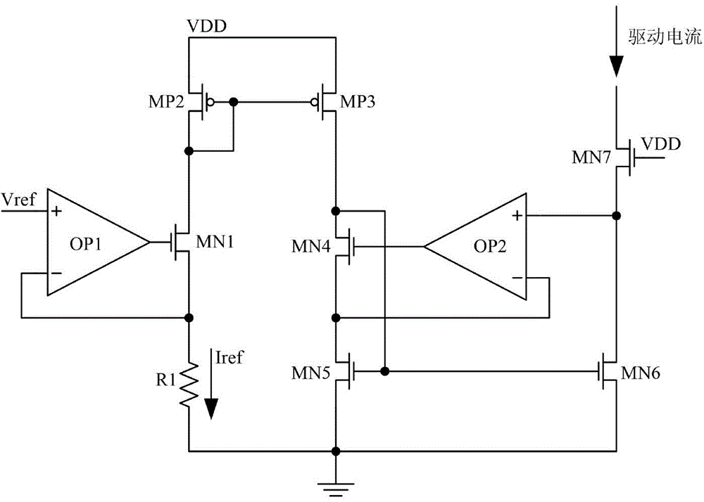
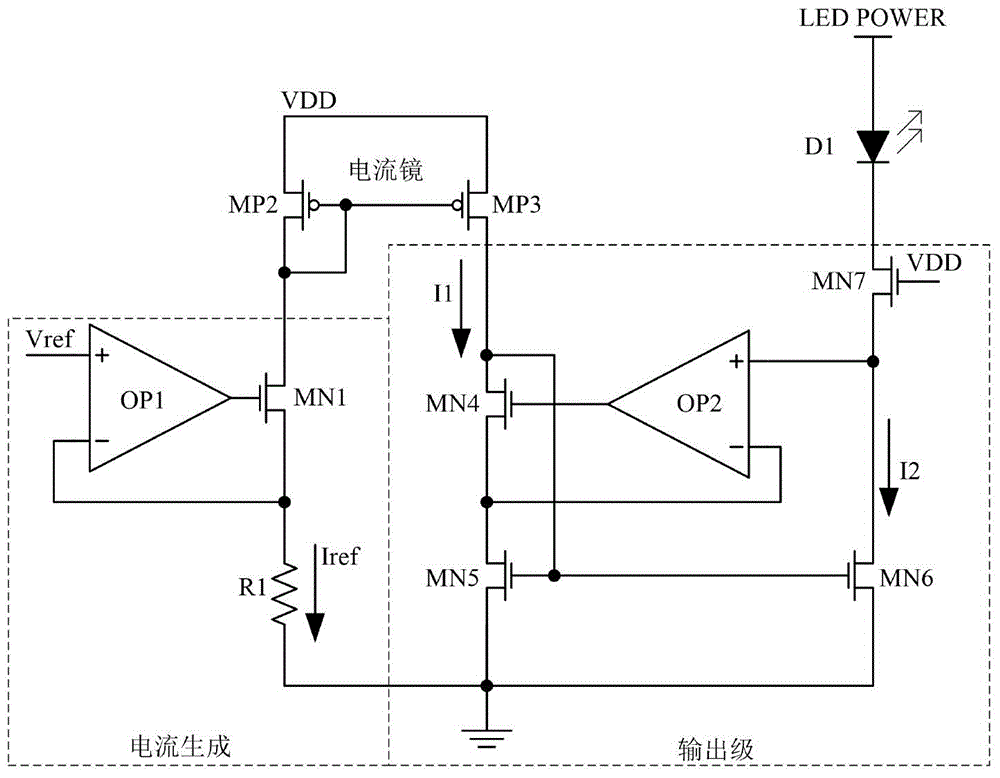
[0024] refer to figure 2 , the present invention includes a current generation circuit 1 , a current mirror 2 and an output stage circuit 3 . in:

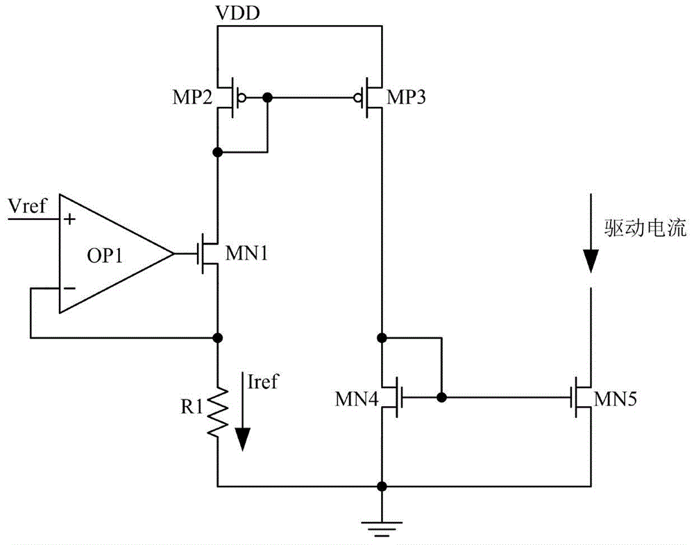
[0025] The current generating circuit 1 includes a first operational amplifier OP1, a resistor R1 and a first NMOS transistor MN1, wherein the positive phase input terminal of the first operational amplifier OP1 is connected to the reference voltage Vref, and its negative phase input terminal is connected to the first NMOS transistor MN1. The source of the tube MN1, its output terminal is connected to the gate of the first NMOS tube MN1; the source of the first NMOS tube MN1 is connected to the resistor R1, and its drain is connected to the drain of the second PMOS tube MP2;

[0026] The current mirror 2 includes a second PMOS transistor MP2 and a third PMOS transistor MP3, wherein the gate of the second PMOS tra...


PUM


Abstract

The invention discloses an infrared light emitting diode driving circuit for infrared approach sensors. By the aid of the infrared light emitting diode driving circuit, the problem of great influence of change of anode voltages of existing infrared light emitting diodes on output currents of existing infrared light emitting diode driving circuits mainly can be solved. The infrared light emitting diode driving circuit comprises a current generating circuit (1), a current mirror (2) and an output-level circuit (3). Reference voltages are applied to two ends of a resistor by the current generating circuit (1) to generate reference currents, and the currents are mirrored to the output-level circuit (3) by the current mirror (2). The infrared light emitting diode driving circuit has the advantages that the output-level circuit (3) forces drain-source voltages of two NMOS (n-channel metal oxide semiconductor) transistors of the output-level current mirror to be consistent with one another by the aid of a negative-feedback loop, the negative-feedback loop comprises an operational amplifier and an NMOS transistor, accordingly, the currents can be accurately mirrored, and the driving circuit is excellent in linear regulation and high in swing and can be used for the infrared approach sensors.

Description

technical field [0001] The invention belongs to the technical field of electronic circuits, relates to an infrared light-emitting diode driving circuit, and can be used in an infrared proximity sensor. Background technique [0002] Many electronic devices, such as smart phones, tablet computers, etc., use proximity sensors to turn off the display in certain occasions, such as answering a call, to prevent misuse, or to control backlight to improve power consumption efficiency. Due to low power consumption and small area, infrared proximity sensors are widely used in the above electronic devices. The infrared proximity sensor has an infrared light-emitting diode IR LED, which emits infrared light, and the proximity sensor senses the intensity of the infrared light reflected by the object to judge the distance of the object relative to the sensor, so the infrared proximity sensor The accuracy is closely related to the brightness of the infrared light-emitting diode, in view of...

Claims


Application Information

Patent Timeline
IPC IPC(8): H03K17/945
Inventor 史凌峰陈森师振波王子铭吕欢欢张飞
Owner XIDIAN UNIV
Why Eureka
Try Eureka