
Multi-pole permanent magnet brushless DC motor and steering gear for steering gear

A permanent magnet DC and brushless motor technology, which is applied in the direction of synchronous machine parts, magnetic circuit rotating parts, magnetic circuit static parts, etc., can solve the problems of low rotation angle accuracy, low output power, and rotation breakage of steering gears , to achieve the effects of improving the precision of magnetic induction and rotation control, small magnetic flux leakage coefficient and high utilization rate

Inactive Publication Date: 2018-10-30
CHANGSHA METRIC ELECTRIC TECH CO LTD
View PDF11 Cites 0 Cited by
  • Summary
  • Abstract
  • Description
  • Claims
  • Application Information

AI Technical Summary

Problems solved by technology

[0004] The invention provides a multi-pole permanent magnet brushless DC motor and a steering gear used for steering gears to solve the problem that the resolution of the rotation angle of the output shaft of the steering gear is limited by the controllable rotation angle of the motor in the existing steering gear motor , the rotation angle accuracy of the steering gear is low; the single-pole structure is adopted, and the output power is low; and when the permanent magnet is magnetized as a whole (that is, the pole arc coefficient is 1), it is easy to leak magnetic flux. The technical problem that the magnetization arc is large and the rotation is broken

Method used


Image

  • Multi-pole permanent magnet brushless DC motor and steering gear for steering gear
  • Multi-pole permanent magnet brushless DC motor and steering gear for steering gear

Examples


Embodiment Construction

[0022] The embodiments of the present invention will be described in detail below with reference to the accompanying drawings, but the present invention can be implemented in various ways defined and covered.

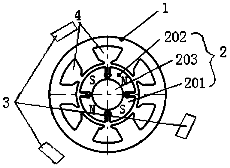
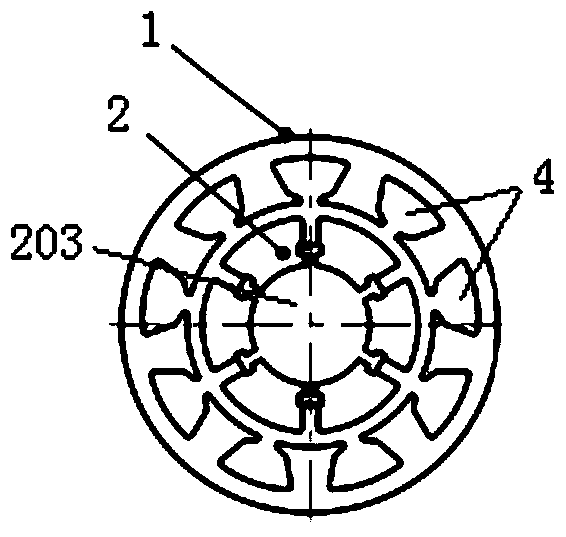
[0023] figure 1 It is one of the structural schematic diagrams of the multi-pole permanent magnet brushless DC motor used for steering gear according to the preferred embodiment of the present invention; figure 2 It is the second structural schematic diagram of the multi-pair pole permanent magnet brushless DC motor used for steering gear in the preferred embodiment of the present invention.

[0024] Such as figure 1 As shown, the multi-pole permanent magnet brushless DC motor used for steering gear in this embodiment includes a stator 1 fixed in the motor housing, a rotor 2 arranged in the stator 1, and a rotor 2 arranged along the circumference of the rotor 2 and used for The sensor 3 that senses the change of magnetic poles during the rotation of the rotor 2 and s...


PUM


Abstract

The invention discloses a multi-pole permanent magnet DC brushless motor used for steering gear and the steering gear. A multi-pole permanent magnet brushless DC motor for steering gear, including a stator fixed in the motor housing, a rotor set in the stator, and a sensor arranged along the circumference of the rotor and used to sense the pole change during the rotation of the rotor and send out signals The sensor, the rotor includes a plurality of tile-type permanent magnets used to increase the magnetic induction density of the steering gear to improve the rotation control accuracy of the steering gear, and the multi-piece tile-type permanent magnets are arranged equidistantly along the circumference of the rotor and fixed to the rotor of the rotor On the core, the shapes of the tile-type permanent magnets are the same. The tile-type permanent magnets are south pole permanent magnets or north pole permanent magnets. One south pole permanent magnet and one north pole permanent magnet form a pair of magnetic poles, and the rotor contains at least two pairs of magnetic poles. The tile-type permanent magnet can be assembled and then magnetized along the rotor circumference at one time, or it can be magnetized separately and then assembled. The assembly process is simple, the magnetic flux leakage coefficient is small, the air gap magnetic density is high, and the utilization rate of the permanent magnet is higher.

Description

technical field [0001] The invention relates to the field of control devices, in particular to a multi-pair pole permanent magnet brushless DC motor used for steering gear. In addition, the present invention also relates to a steering gear comprising the above-mentioned multi-pole permanent magnet brushless DC motor for steering gears. Background technique [0002] The steering gear is an automatic control system composed of a DC drive motor, a reduction gear set, a sensor and a control circuit. When the steering gear is in working condition, according to the received external control signal or instruction, the control part of the steering gear can accurately control the output terminal to rotate at a certain speed within the set rotation angle and under the load condition. angle or position. [0003] Most of the existing steering gears use single-pole motors. The resolution of the rotation angle of the output shaft of the steering gear is limited by the controllable rotat...

Claims


Application Information

Patent Timeline
Patent Type & Authority Patents(China)
IPC IPC(8): H02K21/14H02K21/02H02K1/27H02K1/28H02K1/16
CPCH02K1/27H02K21/14
Inventor 刘国生刘心念毛建瓴
Owner CHANGSHA METRIC ELECTRIC TECH CO LTD
Learn More