Rotor Pivot System

一种转子、枢转的技术,应用在容器、工作台、支承机器等方向,能够解决限制转子枢转系统可应用性等问题,达到良好载荷分布、灵活使用、改进稳定性和耐久性的效果

Inactive Publication Date: 2017-12-15
SIEMENS AG
View PDF3 Cites 0 Cited by
  • Summary
  • Abstract
  • Description
  • Claims
  • Application Information

AI Technical Summary

Problems solved by technology

[0003] A disadvantage of the known rotor pivoting system is that its use presupposes at least an industrial peripheral device in the form of an industrially produced base on which a steering stand and at least one support stand are arranged and forces can be transferred between Introduced in the base via the turntable when the rotor is erected
However, since such peripheral devices are not always present, the applicability of the known rotor pivoting systems is limited

Method used


Image

  • Rotor Pivot System
  • Rotor Pivot System
  • Rotor Pivot System

Examples


Embodiment Construction

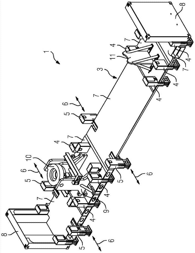
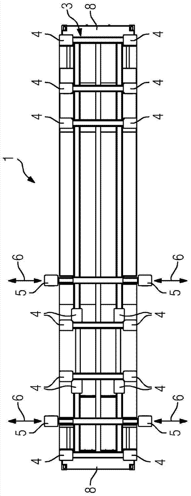
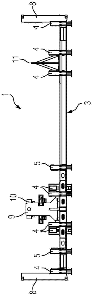
[0031] The figures show a rotor pivot system 1 according to an embodiment of the invention for erecting a rotor, for example for erecting a gas turbine rotor 2 . The rotor pivoting system 1 comprises a heavy-duty frame 3 provided with a plurality of supporting feet 4 and 5 which can be moved out vertically, respectively. The support feet 5 can also be moved out horizontally in the direction of the arrow 6 in order to improve the durability of the heavy duty frame 3 if required. The actuation of the support feet 4 and 5 is currently performed hydraulically, wherein of course alternative actuation variants are also conceivable. On a heavy-duty frame 3 , which can be formed, for example, as a steel frame, a plurality of base plates 7 are held, which define a walkable surface. On its end sides, the heavy-duty frame is provided with an end wall 8 whose dimensions are chosen such that it essentially corresponds to the end wall of a standard container, the current ISO 49' container,...


PUM


Abstract

The invention relates to a rotor pivoting system for erecting a rotor, in particular a gas turbine rotor, for performing maintenance and / or repair work, comprising a steering stand having pivoting means arranged thereon; and at least one Support stand, wherein the rotor pivot system has a heavy-duty frame provided with a plurality of vertically removable support feet and accommodates the steering stand and the support stand, the heavy-duty frame is constructed in a transportable manner and is designed for : When erecting the rotor arranged on the steering stand and the support stand, forces are introduced via the support feet into the base, on which the heavy-duty frame is positioned. Furthermore, the invention relates to a method for carrying out maintenance and / or repair work on a rotor of a machine, in particular on a gas turbine rotor, with the rotor pivoting system according to the invention.

Description

technical field [0001] The invention relates to a rotor pivoting system for erecting a rotor, in particular a gas turbine rotor, for performing maintenance and / or repair work, comprising a steering stand having pivoting means arranged thereon; and at least one Support pedestal. Background technique [0002] Maintenance and / or repair work on the rotor is advantageously performed when it is in a vertical position. In particular, the destacking of gas turbine rotors is considerably simplified in this way. Rotor pivoting systems are used in the prior art for erecting rotors with a high dead weight. It includes a steering stand having pivot means disposed thereon; and at least one support stand. The steering platform and the support platform are established in a first step on the industrial workshop floor and aligned with each other, wherein at least the steering platform is anchored to the workshop floor by means of suitable fastening means. In a further step, the rotor to b...

Claims


Application Information

Patent Timeline
Patent Type & Authority Patents(China)
IPC IPC(8): F01D25/28F02C7/20B65D90/14B65D88/12B25H1/18
CPCF02C7/20F05D2250/411F05D2230/70F05D2230/68F05D2240/20Y10T29/49318F01D25/285B25H1/18B65D88/12B65D90/14B25H1/00F01D25/28F01D25/34F16M5/00F01D5/005F05D2230/72F05D2230/80F05D2260/02
Inventor 马蒂亚斯·里希特马库斯·罗赫利策尔
Owner SIEMENS AG
Why Eureka
Try Eureka