
Sealing bottle plug

A bottle stopper and stopper body technology, applied in the field of sealing bottle stoppers, can solve problems such as loss of seal, affecting the quality of objects in the bottle, and difficulty in ensuring the sealing effect of the bottle mouth.

Active Publication Date: 2015-07-22
刘婷婷
View PDF7 Cites 14 Cited by
  • Summary
  • Abstract
  • Description
  • Claims
  • Application Information

AI Technical Summary

Problems solved by technology

In order to obtain a better sealing performance for the bottle mouth, someone invented an expansion-type bottle stopper (Notice No. 101372274). A moving member, the body member can be used for the first section of longitudinal movement, the elastic member is longitudinally expanded, so that it is firmly attached to the inner wall of the container opening, and the body member can be used for the second The longitudinal movement of the section makes the elastic member shrink radially so that the bottle stopper can be easily taken out from the opening of the container. Although this kind of bottle stopper has a good cork function, it can only be used for Containers of one specification and caliber are used together and have the characteristics of one-time use
When the substance in the bottle needs to be kept for next use in daily life, or the empty bottle is used for secondary use, because the bottle stopper is for one-time use, the seal of the bottle mouth loses the original matching bottle stopper, and it is necessary to find Other bottle stoppers can be used instead, but other stoppers may not just fit the bottle mouth, so it is difficult to ensure that the bottle mouth achieves a good sealing effect, which affects the quality of the objects in the bottle

Method used


Image

  • Sealing bottle plug
  • Sealing bottle plug
  • Sealing bottle plug

Examples


Embodiment Construction

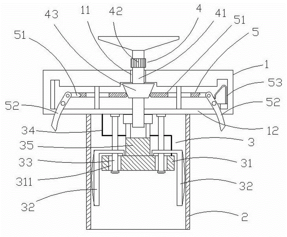
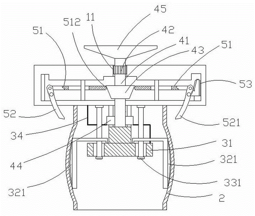
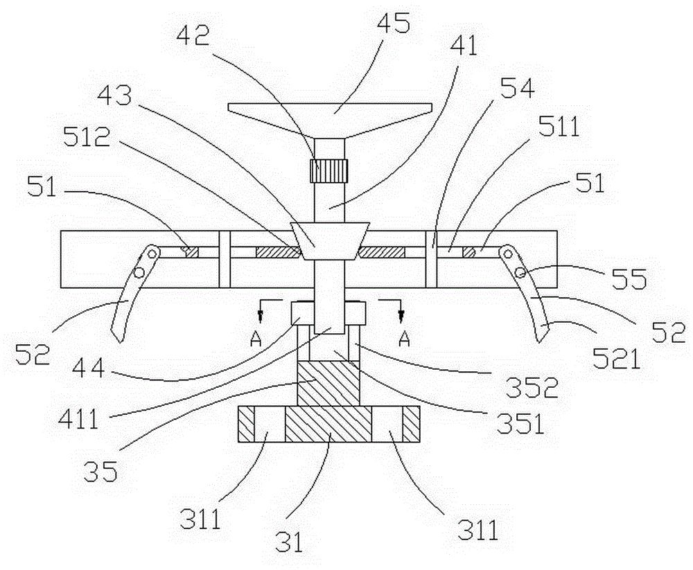
[0017] like figure 1 As shown in -6, a sealed bottle stopper includes an upper cover body 1, an elastic plunger body 2, an expansion mechanism 3, a rotation mechanism 4, and a locking member 5. The upper cover is connected with the elastic plunger body, the elastic plunger body 2 is made of plastic material, the bottom of the elastic plunger body is sealed and integrated with the body, and the inner cavity of the elastic plunger body 2 is provided with an expansion mechanism 3 The drive plate 31 of the expansion mechanism is provided with four support arms 32 equally arranged around the circumference, the connecting portion 323 of the support arm is clamped on the drive plate 31, and the outer surface of the pressing portion 321 of the support arm longitudinally surrounds the elastic column The inner peripheral walls of the plug body 2 are in contact with each other, and the positioning guide pin 33 fixed on the baffle plate 12 passes through the crosspiece 322 of the support ...


PUM


Abstract

The invention discloses a sealing bottle plug. An expansion mechanism is arranged in an inner cavity of an elastic plunger body of the bottle plug. Four circumferentially-arranged supporting arms are arranged on a drive disc of the expansion mechanism. Jacking parts of the supporting arms surround the inner circumferential wall of the elastic plunger body and abut against the inner circumferential wall. When a rotary handle of a rotating mechanism drives the drive disc to rotate, the supporting arms expand and shrink radially to drive the elastic plunger body to shrink and expand radially at the unequal amount; in order to lock the expansion diameter of the elastic plunger body, a locking disc on the rotary handle is moved downwards to be clamped with a locking hole, and meanwhile, a conic control column pushes two clamping hooks of a clamping component to shrink towards each other, so that a bottle opening is clamped, and the bottle opening is sealed and clamped. By the adoption of the sealing bottle plug, according to bottle bodies of different calibers, the bottle plug is adjusted to be matched with bottle openings, the sealing performance is high, reuse is achieved, and practicality is high.

Description

technical field [0001] The invention relates to a bottle stopper, in particular to a sealing bottle stopper. Background technique [0002] Bottles and cans are widely used in daily life. These containers cannot be sealed without a cork. The structure and quality of the cork are related to whether the contents in the container can be preserved for a long time. In order to obtain a better sealing performance for the bottle mouth, someone invented an expansion-type bottle stopper (Notice No. 101372274). A moving member, the body member can be used for the first section of longitudinal movement, the elastic member is longitudinally expanded, so that it is firmly attached to the inner wall of the container opening, and the body member can be used for the second The longitudinal movement of the section makes the elastic member shrink radially so that the bottle stopper can be easily taken out from the opening of the container. Although this kind of bottle stopper has a good cork ...

Claims


Application Information

Patent Timeline
Patent Type & Authority Applications(China)
IPC IPC(8): B65D39/12
Inventor 蒋祥初
Owner 刘婷婷
Learn More