
An assembly jig and assembly method of square iron and coil of moving iron unit

A technology for assembling jigs and coils, applied to electrical components, sensors, etc., can solve the problems of low assembly efficiency and high defective rate, and achieve the effects of accurate and convenient positioning, easy removal, and convenient disassembly

Active Publication Date: 2018-04-10
CHANGZHOU AMT
View PDF7 Cites 0 Cited by
  • Summary
  • Abstract
  • Description
  • Claims
  • Application Information

AI Technical Summary

Problems solved by technology

[0005] The purpose of the present invention is to overcome the shortcomings of low assembly efficiency and high defective rate of the existing moving iron unit square iron and coil, and provide an assembly jig and assembly method for the moving iron unit square iron and coil, using the technology of the present invention The scheme uses a special jig to position the induction coil and the square iron separately, and then combines the square iron and the induction coil with glue. After the square iron and the induction coil are firmly connected, it is easy to remove, which not only improves the product qualification rate, but also improves the manufacturing process. Efficiency, easy to achieve mass production

Method used


Image

  • An assembly jig and assembly method of square iron and coil of moving iron unit
  • An assembly jig and assembly method of square iron and coil of moving iron unit
  • An assembly jig and assembly method of square iron and coil of moving iron unit

Examples


Embodiment

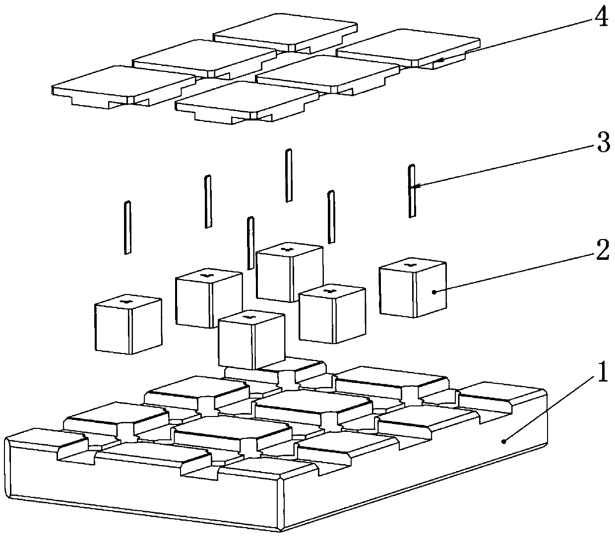
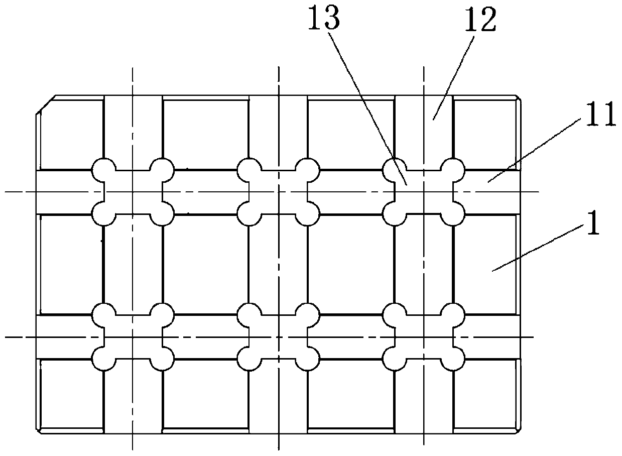
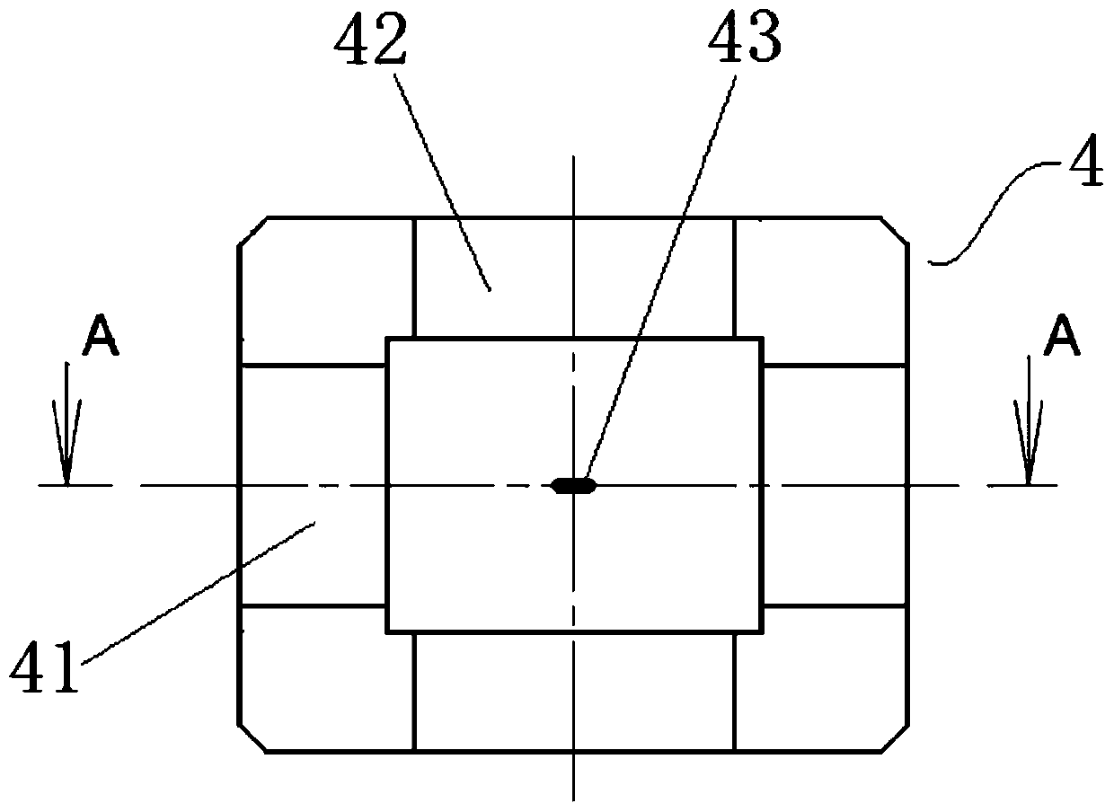
[0038] Combine Figure 1 to Figure 4 As shown, the assembly jig for square iron and coil of the moving iron unit of this embodiment includes a bottom plate 1 and a carrier board 4, the bottom plate 1 is used to install the positioning square iron, and the carrier 4 is used to install the positioning induction coil. Among them, such as figure 2 As shown, the bottom plate 1 is provided with one or more horizontal mating grooves 11 and one or more longitudinal mating grooves 12, the horizontal mating grooves 11 and the longitudinal mating grooves 12 are perpendicular to each other, forming a rectangular array arrangement In the cross position of the horizontal inserting groove 11 and the longitudinal inserting groove 12, an insert fixing groove 13 is provided. The insert fixing groove 13 is provided with an insert 2, and the middle of the insert 2 is provided with a square iron for positioning The insert 3 is a rod-shaped component inserted in the through hole provided on the ins...


PUM


Abstract

The invention discloses an assembly jig and an assembly method for a moving iron unit square iron and a coil, belonging to the field of tooling jigs. A moving iron unit square iron and coil assembly jig according to the present invention includes a base plate for installing and positioning the square iron and a carrier plate for installing and positioning induction coils, and the base plate and the carrier plate pass through the mating groove and the mating protrusion The blocks are matched together, and the positioning is accurate, so that the square iron and the induction coil are accurately positioned and connected, which overcomes the shortcomings of the through-type assembly, such as the difficulty in removing the fixed core, and the easily damaged coil. The efficiency is improved, and the production efficiency is improved, which is convenient for mass production. The invention also discloses a method for assembling the square iron and the coil of the moving iron unit. The above-mentioned special jig is used to position the induction coil and the square iron respectively, and the positioning is accurate. The product is easy to take off, realizing assembly line production, greatly improving production efficiency and product quality.

Description

Technical field [0001] The invention relates to a manufacturing jig and a manufacturing method of a moving iron unit, and more specifically, to an assembling jig and an assembly method of a square iron and a coil of a moving iron unit. Background technique [0002] The moving iron unit has the advantages of good sound insulation, small size and high sensitivity, and has been widely used in headphones and speakers. Compared with the moving coil unit, the frequency response curve of the moving iron unit is more stable, and the earphones using the moving iron unit are more helpful for hearing protection. The magnetic drive mechanism of the moving iron unit is mainly composed of a balanced armature, a square iron (yoke iron), an induction coil and a permanent magnet. The permanent magnets are symmetrically arranged in the square iron to form a vibration space for the balanced armature, and the balanced armature passes through In the middle of the two permanent magnets, one end is pr...

Claims


Application Information

Patent Timeline
Patent Type & Authority Patents(China)
IPC IPC(8): H04R31/00
Inventor 魏鹏孟献振曾伟
Owner CHANGZHOU AMT
Learn More