
Method and system for controlling power output of an inverter

A technology of power output and maximum power output, applied in control/regulation systems, converting irreversible DC power input to AC power output, instruments, etc. cost saving effect

Inactive Publication Date: 2015-07-15
NIDEC CONTROL TECHN LTD
View PDF10 Cites 24 Cited by
  • Summary
  • Abstract
  • Description
  • Claims
  • Application Information

AI Technical Summary

Problems solved by technology

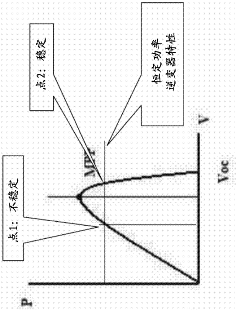
[0005] (a) the cost of allowing the voltage to rise and accepting a higher voltage-rated inverter, or otherwise resizing the system to reduce the voltage, both of which result in higher costs;
[0006] (b) using an extra resistor to dissipate unnecessary power with a controller such as a "chopper" (see e.g. US2010 / 0275966) - this is expensive and requires facilities to dissipate the heat generated in the resistor, and are therefore not practical in large systems

Method used


Image

  • Method and system for controlling power output of an inverter
  • Method and system for controlling power output of an inverter
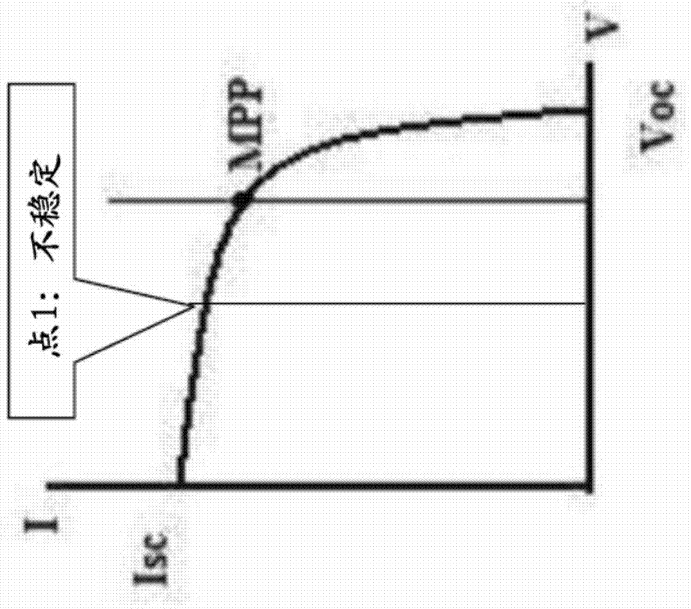
  • Method and system for controlling power output of an inverter

Examples


Embodiment Construction

[0022] The present invention seeks to provide an improved method and system for controlling the power output of an inverter. While various embodiments of the invention are described below, the invention is not limited to these embodiments and variations of these embodiments may well fall within the scope of the invention which is limited only by the appended claims.

[0023] Before describing embodiments of the present invention in detail, a brief discussion of the operation of a typical prior art inverter follows.

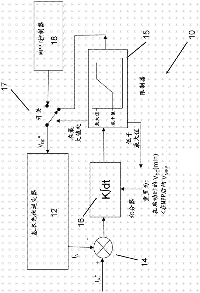
[0024] Typically, the inverter operates with an internal control loop that adapts the active component of the output current to the output current to give a desired reference value for the DC input voltage. The above loop works so that if the voltage increases the active current increases, which in turn increases the inverter input current and corrects for voltage variations. In the usual MPP tracking mode, this reference voltage is continuously modulated to find...


PUM


Abstract

According to a first aspect of the invention, there is provided a method of controlling a power output of an inverter (12). The method comprises measuring an output current (I A ) of the inverter (12), determining a difference between the output current (I A ) and a reference current (I A *), and controlling a reference input voltage (V DC *) of the inverter (12) as a function of the determined difference. In a second aspect of the invention, there is described a system (10) for controlling a power output of an inverter (12). The system comprises an inverter (12) arranged to output a current (I A ) as a function of a reference input voltage (V DC *). The system (10) further comprises a controller (14, 16) arranged to determine a difference between the output current (I A ) and a reference current (I A *). The controller (14, 16) is further arranged to control the reference input voltage (V DC *) as a function of the determined difference. The method may allow for control of a photovoltaic inverter at a power less than its maximum capability for a given solar irradiation, which may avoid the problem of the photovoltaic array voltage rising above a level where the inverter can run.

Description

technical field [0001] The invention relates to a method and a corresponding system for controlling the power output of an inverter, especially a photovoltaic inverter. In particular, the invention relates to a method and system for limiting the power output of an inverter. Background technique [0002] Traditionally, photovoltaic inverters operate at the maximum power point (MPP) to maximize revenue from solar panel factories. For example, in US2013 / 0155735, in figure 2 In B is shown a control system that controls the inverter such that the PV array voltage is kept at the optimum level required by the maximum power point. An integral controller (PI control) and a limiter are part of the inverter's internal control arrangement, which enables it to track the desired MPP voltage. [0003] However, recently, there are cases where the inverter output power must be limited below the MPP. For example, this may be because the power company has issued an order to limit the outpu...

Claims


Application Information

Patent Timeline
IPC IPC(8): H02J3/38H02M7/48
CPCG05F1/67H02M7/44H02S40/32Y02E10/56H02J3/385
Inventor 科林·哈吉斯
Owner NIDEC CONTROL TECHN LTD
Learn More