Separated type switch socket

A separate and switchable technology, applied in the installation of electrical components, coupling devices, connecting parts, etc., can solve the problems of increasing the difficulty and cost of on-site construction, wall damage, panel damage, etc., and achieve safe and convenient replacement and maintenance Effect

Inactive Publication Date: 2015-07-15
黎辉
View PDF6 Cites 8 Cited by
  • Summary
  • Abstract
  • Description
  • Claims
  • Application Information

AI Technical Summary

Problems solved by technology

[0003] Conventional switch sockets are used to directly connect the AC power supply line to the back seat of the switch socket panel, but if you want to perform fault maintenance on the switch socket panel or replace the product, you must use tools to disassemble it from the power supply line. Every disassembly and assembly will cause damage to the wall body, and there will be great safety hazards for the construction personnel. At the same time, it will also increase the difficulty and cost of on-site construction.
[0004] In addition, during building decoration, installing the switch socket panel prematurely will cause damage to the panel during the construction process, but if it is not installed in advance, it may cause the exposed power supply line in the wall bottom box to damage the safety belt of the construction personnel. to hidden danger

Method used


Image

  • Separated type switch socket
  • Separated type switch socket
  • Separated type switch socket

Examples


Embodiment 1

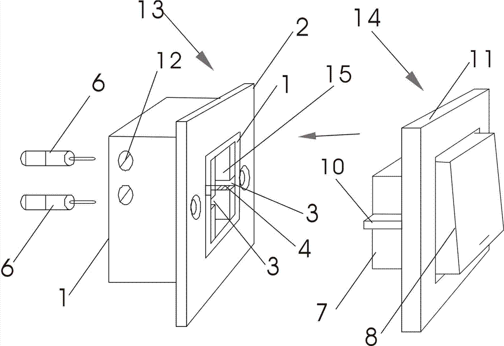
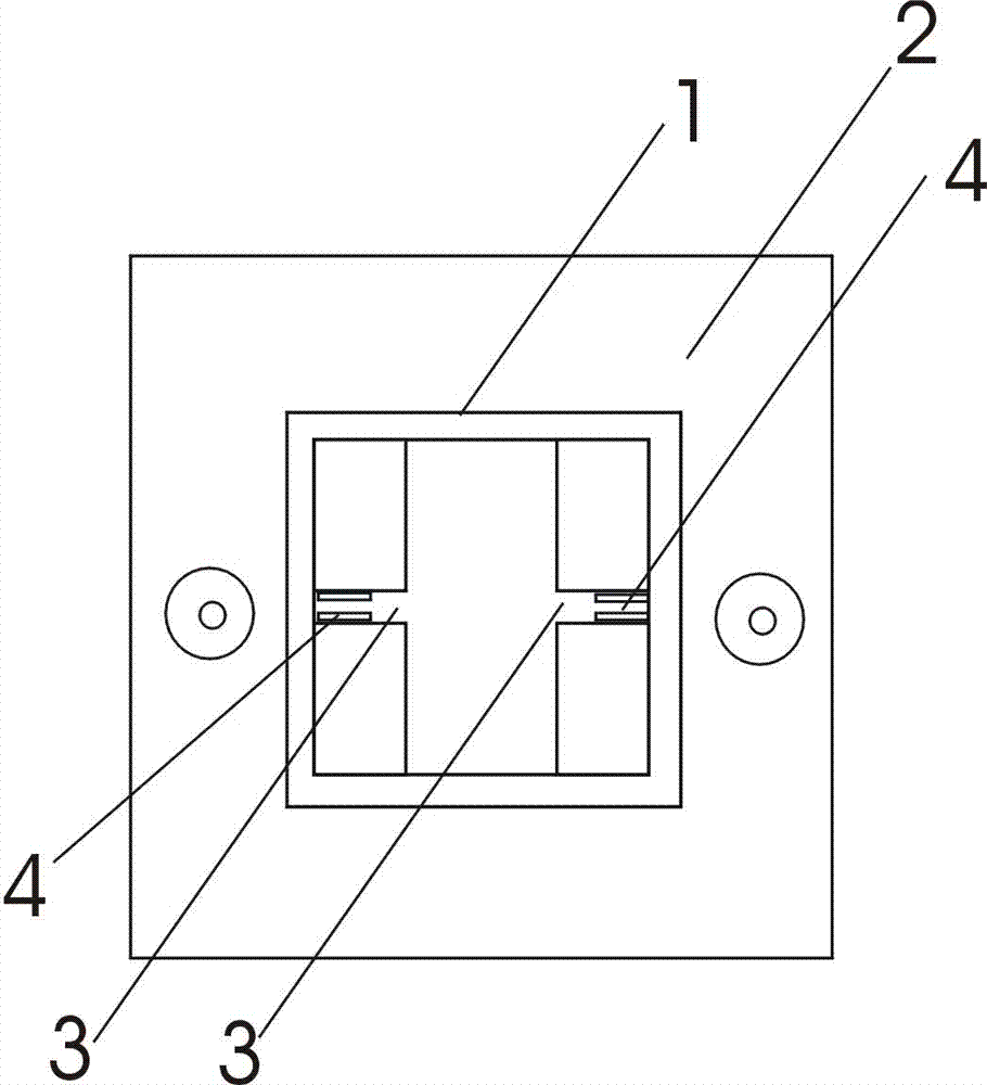
[0019] Example 1: see Figure 1-6 , a separate switch socket, including a junction bottom box 13, a panel 14, the junction bottom box 13 includes a wiring base 1 and a mounting bracket 2 installed in the wiring base 1, the mounting bracket 2 is located at the front end of the wiring base 1, and the installation A through hole in the middle of the bracket 2 communicates with the hollow structure 15 .

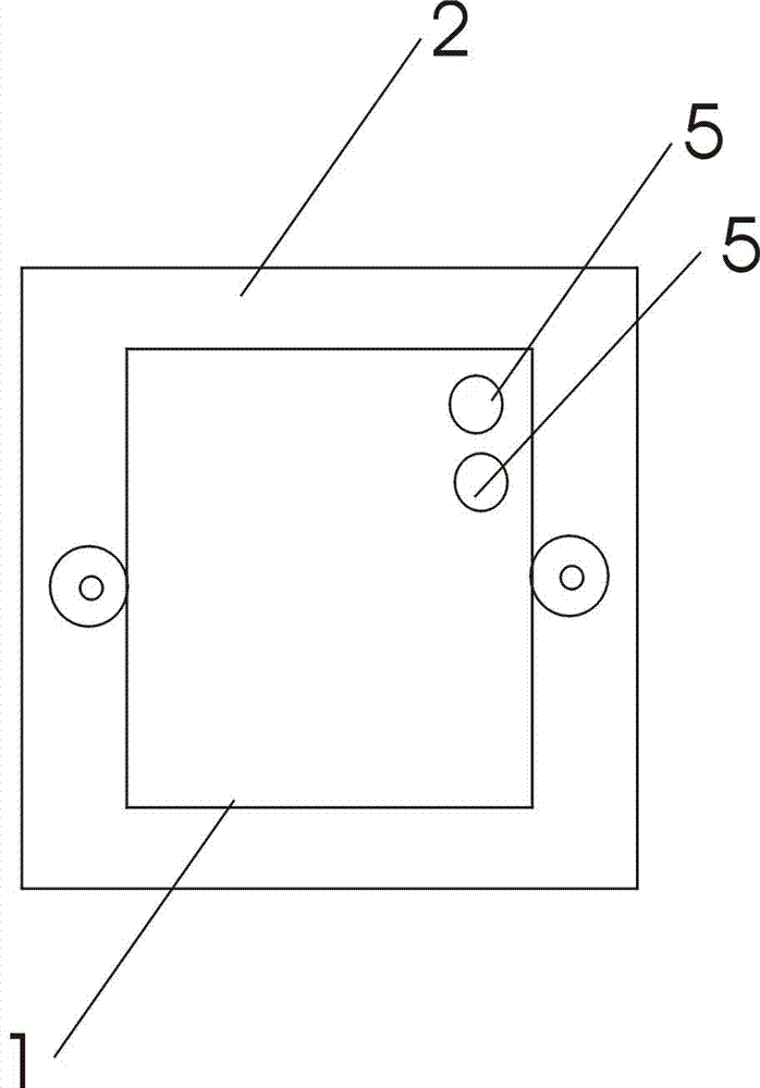
[0020] The terminal base 1 is a hollow structure 15, and there are at least two insertion grooves 3 on the inner wall of the hollow structure 15, and the insertion grooves 3 respectively hide metal contacts 4, and the metal contacts 4 are respectively It is electrically connected with the two base terminals 5.

[0021] The panel 14 includes a rear seat 7 connected to a switch button 8 or connected to a socket hole 9 .

[0022] There are at least two exposed metal protrusions 10 on the outside of the rear seat 7, and an insulating frame 11 for fixing the panel is set around the ...

Embodiment 2

[0028] Example 2: see Figure 7 , The difference from Embodiment 1 is that the back seat 7 is connected to the socket hole 9, and there is a line in the back seat 7 connected to the metal protrusion 10.

[0029] In the present invention, a plurality of switch buttons and socket holes can be arranged in the panel 14 at the same time.

[0030] The present invention can be directly installed on the wall body, and can also be installed in the existing switch socket bottom box for use. For example, for a switch socket in an existing installed wall, the existing panel is removed, and the junction bottom box of the present invention is placed in the existing switch socket bottom box.


PUM


Abstract

The invention provides a separated type switch socket. The separated type switch socket comprises a wiring bottom box and a panel. The wiring bottom box comprises a wiring base and an installing support installed in the wiring base. The wiring base is of a hollow structure. The inner wall of the hollow structure is provided with at least two inserting grooves. Metal contact bodies are hidden in the inserting grooves respectively and are electrically connected with two base wiring ends respectively. The panel comprises a back base connected with an on / off button or a socket hole. The outer side of the back base is provided with at least two exposed metal protruding bodies. The periphery of the on / off button or the periphery of the socket hole is sleeved with an insulation frame. The metal protruding bodies are inserted into the inserting grooves and electrically connected with the metal contact bodies. According to the separated type switch socket, the switch panel or the socket panel is separated from a power supply circuit, and the switch panel or the socket panel can be replaced and maintained safely and conveniently without any tool.

Description

technical field [0001] The invention relates to a switch socket, in particular to a separate switch socket. Background technique [0002] Most of the switch sockets are electrical switches and sockets installed on the wall, and are electrical products used to connect and disconnect circuits. [0003] Conventional switch sockets are used to directly connect the AC power supply line to the back seat of the switch socket panel, but if you want to perform fault maintenance on the switch socket panel or replace the product, you must use tools to disassemble it from the power supply line. Every disassembly and assembly will cause damage to the wall body, and there is also a great safety hazard for the construction personnel. At the same time, it also increases the difficulty and cost of on-site construction. [0004] In addition, during building decoration, installing the switch socket panel prematurely will cause damage to the panel during the construction process, but if it is ...

Claims


Application Information

Patent Timeline
Patent Type & Authority Applications(China)
IPC IPC(8): H01R13/514H01R13/73
CPCH01R13/514H01R13/73H02G3/10
Inventor 黎辉
Owner 黎辉
Why Eureka
Try Eureka