


Quick Research
Generate reliable direction feasibility study reports for your R&D in just a few steps.

Technical Q&A
Discover and master advanced knowledge NOW. Basics, ideas, possibilities, all at once.

Find Solutions
As an expert in R&D theories, this can generate solutions to your technical problems instantly.

Evaluate Feasibility
Analyze your overall solution with one click, know your potential R&D risks in advance.

Monitor Landscape
Get weekly tech updates, stay abreast of the latest tech innovations and key insights.
Piezoelectric patch assembled piezoelectric tube
A piezoelectric sheet and assembly technology, applied in the field of piezoelectric components, to achieve the effect of thicker, free inner diameter and low cost
- Summary
- Abstract
- Description
- Claims
- Application Information
AI Technical Summary
Problems solved by technology
Method used
Image

Examples
Embodiment 1
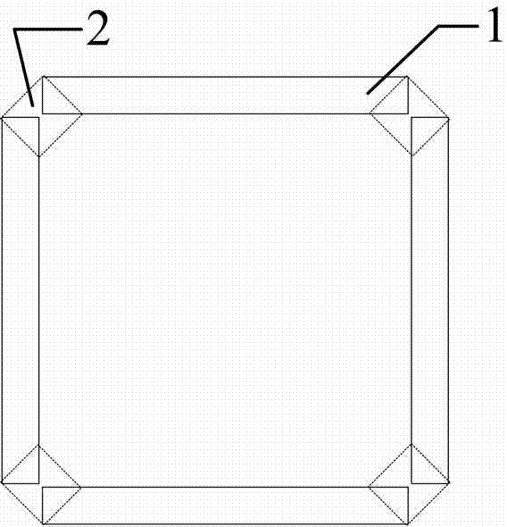
[0042] The most commonly used inner and outer wall electrodes are quartered and the entire gap is fixed on the side of the piezoelectric tube
[0043]Use epoxy resin glue to fix the piezoelectric film, and choose one of them such as 353ND. The four piezoelectric sheets have the same size, are all polarized in the thickness direction, and the two widest surfaces have been plated with electrodes. The size of a single piezoelectric sheet is 20*6*1mm. Adjust the insulating epoxy resin AB glue 353ND according to the instructions in the manual, and assemble the above four piezoelectric sheets 1 into a square structure with a cross section and fix it, and then place the four slits formed by the four pairs of nearest sides Apply the adjusted connector 2 353ND glue, and finally move it into the oven smoothly and bake at 100°C for 10 minutes, so that the above four piezoelectric sheets are cured into a piezoelectric square tube whose inner and outer wall electrodes have been quartered....
Embodiment 2
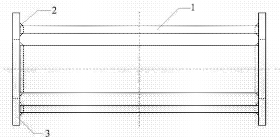
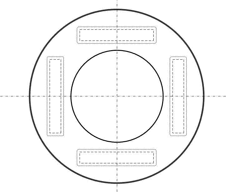
[0047] Piezoelectric tube with both ends fixed by the base plate
[0048] In the above-mentioned embodiment, four pieces of piezoelectric sheets 1, all of which are polarized in the thickness direction, have the same size and have been plated with electrodes, are combined into a structure with a square cross section and fixed, and the upper and lower bottom surfaces are ringed with connectors 2. Oxygen resin cement, such as 353ND glue, forms a piezoelectric body on two bottom plates 3 with a certain hardness. The bottom plate is a sapphire sheet, glass sheet, stainless steel sheet or brass sheet. The shape of the bottom plate is round or square. Such as Figure 2-3 shown. The gaps between the piezoelectric sheets may be fixed by connecting bodies, or may not be fixed by connecting bodies.
Embodiment 3
[0050] Piezoelectric tube fixed only at both ends of the slit
[0051] In Example 2, four piezoelectric sheets 1, all of which are polarized in the thickness direction, have the same size, and have been plated with electrodes, are put together into a structure with a square cross section and fixed, and the gaps at the upper and lower ends are connected with connectors. 2 Epoxy resin adhesive, such as 353ND adhesive, such as Figure 4-6 shown.
[0052] The piezoelectric tube with only the gaps at both ends bonded and fixed by this method is especially suitable for the GeckoDrive piezoelectric motor described in REVIEW OF SCIENTIFIC INSTRUMENTS 84, 056106 (2013) and REVIEW OF SCIENTIFIC INSTRUMENTS 84, 113703 (2013).
PUM
 Abstract
Description
Claims
Application Information
 - R&D Engineer
- R&D Manager
- IP Professional
- Industry Leading Data Capabilities
- Powerful AI technology
- Patent DNA Extraction
Browse by: Latest US Patents, China's latest patents, Technical Efficacy Thesaurus, Application Domain, Technology Topic, Popular Technical Reports.
© 2024 PatSnap. All rights reserved.Legal|Privacy policy|Modern Slavery Act Transparency Statement|Sitemap|About US| Contact US: help@patsnap.com