A method and device for automatic detection of item loading difference
A technology for automatic detection of items, applied in weighing, measuring devices, instruments, etc., can solve problems such as inability to be isolated, unqualified sample groups, etc.
- Summary
- Abstract
- Description
- Claims
- Application Information
AI Technical Summary
Problems solved by technology
Method used
Image
Examples
Embodiment 1
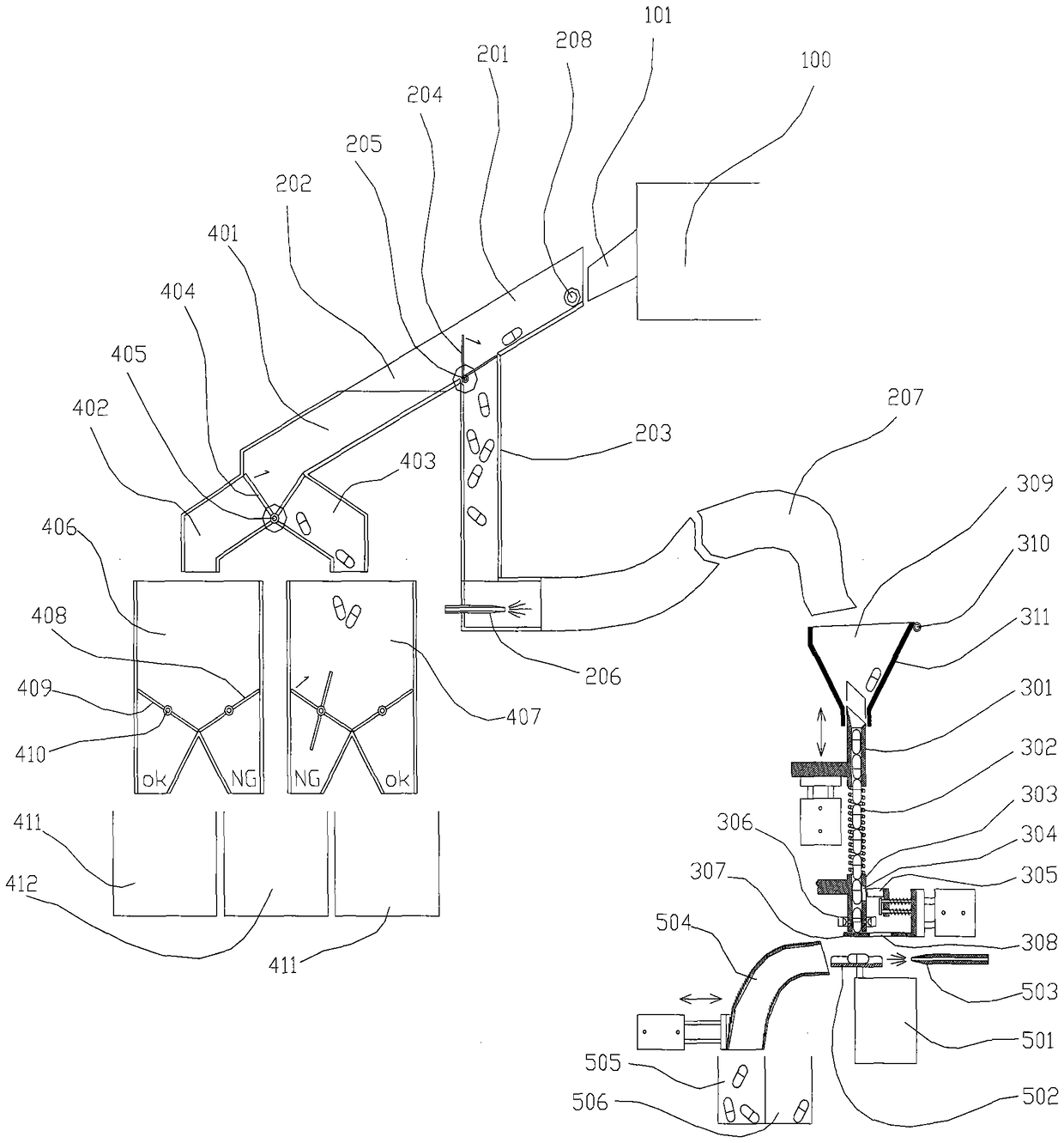
[0172] Such as Figure 2AAs shown, wherein, the sampling device of the article quality index difference automatic detection equipment in the present embodiment includes: the sampling total channel 201 that the inlet is connected with the outlet of the production unit 100, the first channel for detecting whether there is an article coming out from the outlet of the production unit 100 A detection sensor 208 , a sample channel 203 whose inlet is connected to the main sampling channel 201 , and a sampling valve 204 for switching items from the main sampling channel 201 to the sample channel 203 or the non-sample channel 202 . The first detection sensor 208 is used to transmit the detection result to the controller, and the sampling valve 204 is used to perform corresponding operations according to the control signal sent by the controller.
[0173] Wherein the sampling valve 204 can rotate around the sampling valve rotating shaft 205, so that when rotating to a certain position, ...
Embodiment 2
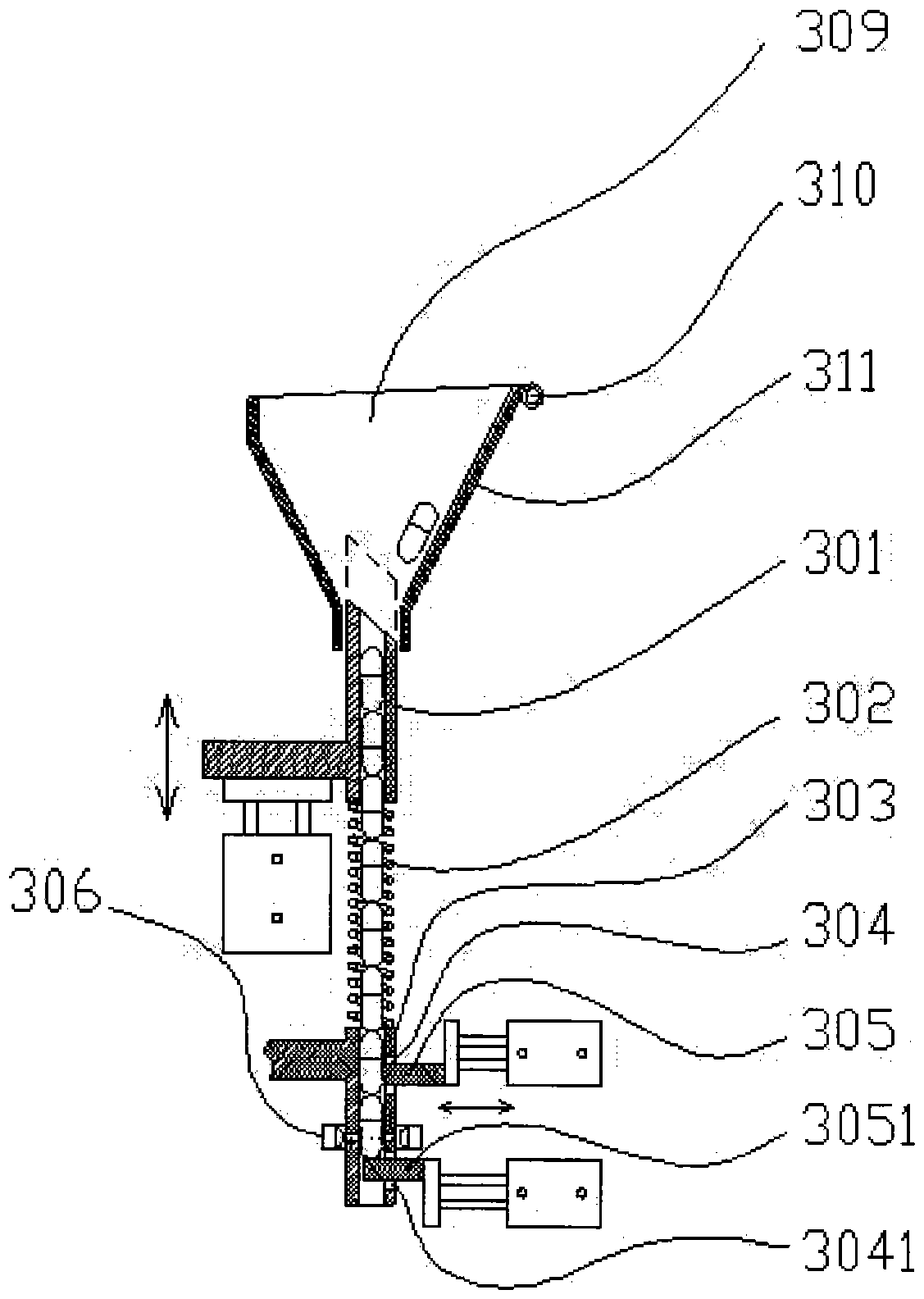
[0190] In Embodiment 2 of the present invention, the difference from Embodiment 1 lies in the weighing device, image 3 Emphasis shows the specific structure of the weighing device in this embodiment, such as image 3 As shown, the weighing device includes a sample hopper 309 for receiving samples output from the outlet of the sample channel 203, a discharge door 311 for discharging excess material, a lower sampling tube 303, and an inlet inserted in the sample hopper and can be inserted along the own length direction ( image 3 Up and down direction shown) moving upper sampling tube 301, the inlet is inserted in the upper sampling tube 301 and the outlet is inserted in the elastic telescopic tube 302 in the lower sampling tube 303, the sampling block 3031 located at the outlet of the lower sampling tube 303, The upper sampling plate 3071 and the lower sampling plate 3072 respectively arranged at the entrance and exit of the sampling block 3031 and the second detection sensor...
Embodiment 3
[0194] In Embodiment 3 of the present invention, the difference from Embodiments 1 and 2 lies in the weighing device, Figure 5 The specific structure of the weighing device is highlighted, such as Figure 5 As shown, the weighing device includes a buffer tray 508 for receiving samples delivered from the weighing device, a weighing tray 502, and a weighing pan for weighing the samples in the weighing tray 502. The unit 501 , the delivery trough 504 for delivering the sample to the first good product container 505 or the first defective product container 506 , and the pushing unit for pushing the sample from the weighing tray 502 to the delivery trough 504 .
[0195] The feeding chute 504 and the containers 505 and 506 can move relatively, and the weighing unit 501 is also used to send the weighing result to the controller, and the controller is used to control the feeding chute 504 or the container according to the analysis results 505, 506 moves. Figure 5 The structure for...
PUM
 Abstract
Description
Claims
Application Information
 - R&D Engineer
- R&D Manager
- IP Professional
- Industry Leading Data Capabilities
- Powerful AI technology
- Patent DNA Extraction
Browse by: Latest US Patents, China's latest patents, Technical Efficacy Thesaurus, Application Domain, Technology Topic, Popular Technical Reports.
© 2024 PatSnap. All rights reserved.Legal|Privacy policy|Modern Slavery Act Transparency Statement|Sitemap|About US| Contact US: help@patsnap.com


