
Oil seal

A technology for oil seals and sealing parts, which is used in engine components, engine seals, mechanical equipment, etc.

Active Publication Date: 2017-08-04
NOK CORP
View PDF2 Cites 0 Cited by
  • Summary
  • Abstract
  • Description
  • Claims
  • Application Information

AI Technical Summary

Problems solved by technology

Therefore, it is necessary to perform an inspection based on setting the leakage allowable value, and a simple inspection cannot be performed by setting the leakage threshold value to zero (a disadvantage due to air release from the fabric)

Method used


Image

  • Oil seal
  • Oil seal
  • Oil seal

Examples


Embodiment Construction

[0058]Next, embodiments of the present invention will be described based on the drawings.

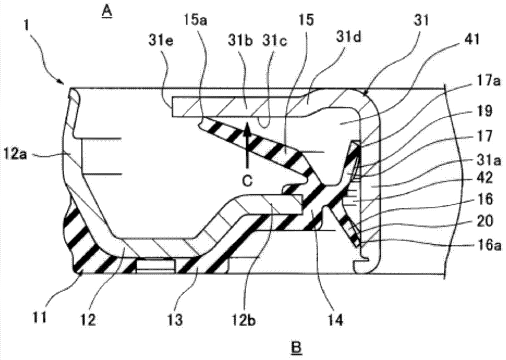
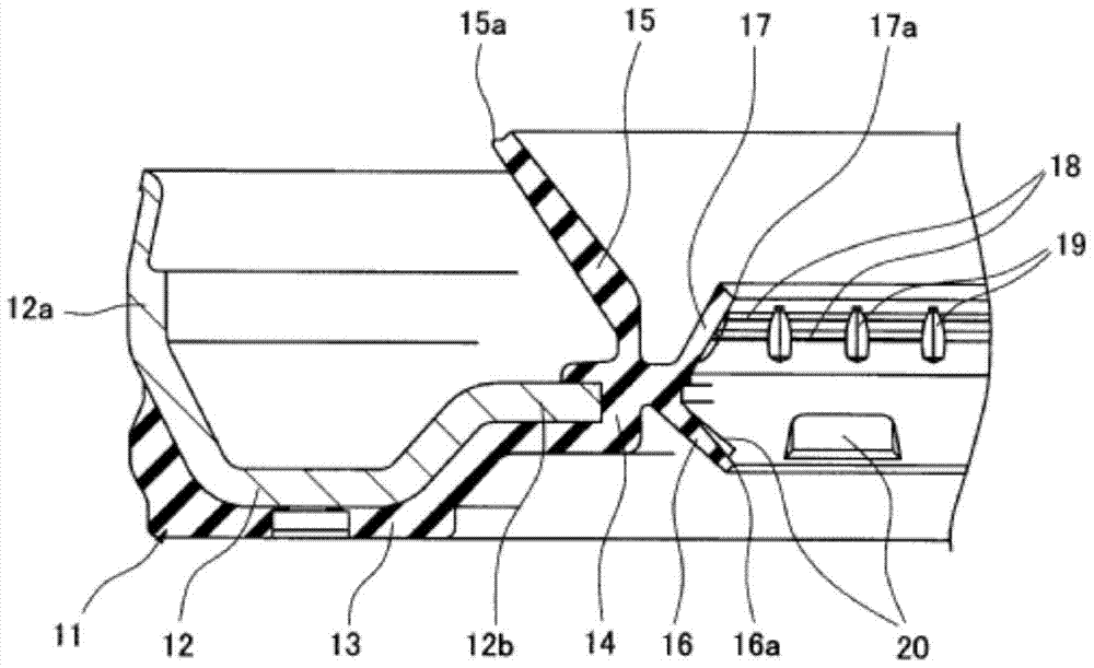
[0059] figure 1 A main part cross section of the oil seal 1 according to the embodiment of the present invention is shown, figure 2 The state before combining the lip seal member 11 and the flinger 31 in the same oil seal 1 is shown.

[0060] figure 1 The oil seal 1 shown in is composed of a lip seal member 11 fixed to the inner periphery of a shaft hole of a casing (not shown), and an oil flinger 31 fixed to a rotating shaft (not shown) inserted through the shaft hole. Combination of these components prevents leakage of sealing fluid from inside A to outside B, and at the same time prevents dust from outside B from entering inside A.

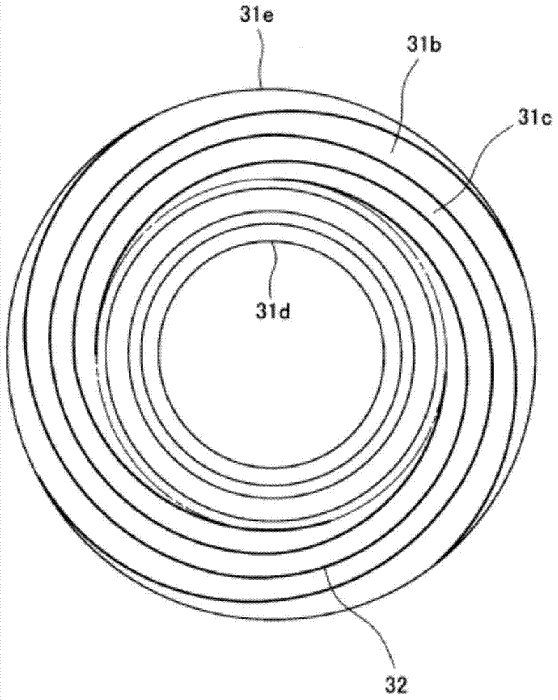
[0061] The oil flinger 31 is made of a metal material, and a flange portion 31b is integrally formed radially outward at the machine inner end portion of the cylindrical portion 31a fitted on the outer peripheral surface of the rotating shaft, and ...


PUM


Abstract

The present invention provides an oil seal capable of reducing a sliding torque as compared with the case of using a fabric as a dustproof lip. In order to achieve this purpose, the flinger has thread grooves facing radially outward on the outer end surface of the flange portion and exerting a suction function. The lip seal member includes a main lip, a dustproof lip made of a rubber-like elastic material, and an intermediate lip also made of a rubber-like elastic material. The middle lip makes the lip end face the inner side of the machine, and the lip end is in close contact with the oil flinger on the entire circumference. Further, at the opposite part to the oil flinger, there is an annular first protrusion and a part of the second ring on the circumference. protrusion. The first protrusion has a structure in which a small gap is formed between the first protrusion and the flinger so that dust hardly passes through the lip end. The second protrusion has a structure that has a portion higher than the first protrusion, and when eccentricity occurs on the rotating shaft, a slight gap is appropriately maintained.

Description

technical field [0001] The present invention relates to an oil seal as one type of sealing device related to sealing technology. The oil seal of the present invention is used, for example, in the field related to automobiles (engines), or in the field of general machinery. Background technique [0002] Such as Figure 4 As shown, an oil seal using a fabric 51 as a dust lip has been known, for example, in the field of automobile engines (diesel engines) for sealing the periphery of a crankshaft. [0003] In this prior art, the fabric 51 is constructed such that its initial inner diameter (the inner diameter before the flinger 52 is inserted) d 1 Set to the outer diameter d of the fabric sliding part of the flinger 52 2 Therefore, the fabric 51 has an interference. When the oil flinger 52 is inserted, the fabric 51 spreads along the oil flinger 52 to ensure the contact width with the oil flinger 52 . [0004] Therefore, here, since the interference amount of the fabric 51 i...

Claims


Application Information

Patent Timeline
Patent Type & Authority Patents(China)
IPC IPC(8): F16J15/3232F16J15/3244F16J15/3264F16J15/3224F16J15/3252
CPCF16J15/164F16J15/3244F16J15/3264F16J15/32F16J15/002F16J15/3204F16J15/44
Inventor 中川岳洋
Owner NOK CORP
Learn More