Sealing device for rolling bearing
A technology for sealing devices and rolling bearings, which is applied to engine seals, ball bearings, bearing components, etc., can solve problems such as difficulty in suppressing water and dust, achieve the effect of suppressing width changes and increasing water resistance
- Summary
- Abstract
- Description
- Claims
- Application Information
AI Technical Summary
Problems solved by technology
Method used
Image
Examples
Embodiment 1
[0087] Hereinafter, the best mode for carrying out the present invention will be described according to the embodiments.
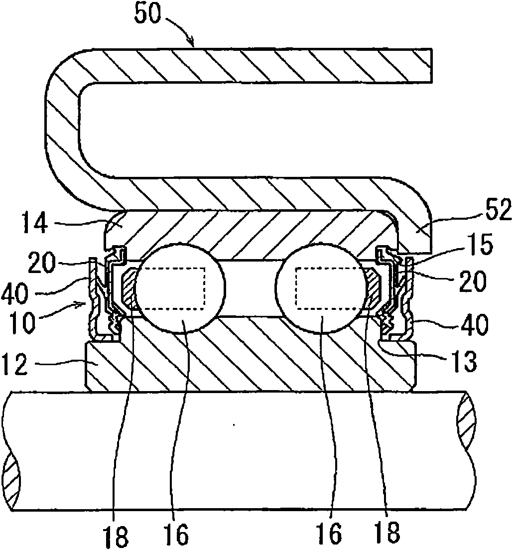
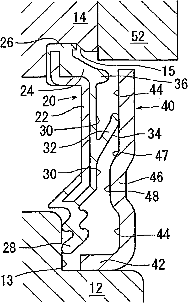
[0088] figure 1 A partial sectional view of an idler 50 used in the rolling bearing 10 including the rolling bearing sealing device according to Embodiment 1 of the present invention is shown. figure 2 show figure 1 An enlarged view of the seal part of the rolling bearing 10 shown.
[0089] as in figure 1 and 2 As shown in , the outer ring rotating type double row ball bearing for idler 50 includes: inner ring 12; outer ring 14; cage 18 for holding double row balls 16, 16; for covering inner ring 12 and a seal 20 in a space defined between the outer ring 14 ; and an oil slinger 40 provided on the side of the seal 20 facing the outer side of the bearing or on the axially outer side of the seal 20 . Among these constituent elements, the inner ring 12 , the outer ring 14 , the seal 20 and the flinger 40 constitute the sealing device of the rolling be...
Embodiment 2
[0104] The configuration of Embodiment 2 of the present invention will be described.
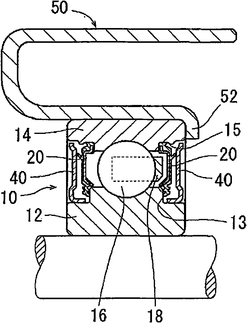
[0105] In the sealing device according to this embodiment, the same reference numerals will be given to the same constituent parts as those of Embodiment 1 already described above, and repeated identical descriptions will be omitted. image 3 A partial sectional view showing an idler 50 using a rolling bearing 10 including a rolling bearing sealing device according to Embodiment 2 of the present invention. Figure 4 shown in image 3 An enlarged view of part of the sealing arrangement in the shown rolling bearing 10 .
[0106] as in image 3 and 4 As shown in , the rolling bearing 10 is an outer ring rolling type single row ball bearing used in an idler 50 .
[0107] as in Figure 4 As shown in , a tapered side lip 30 that expands outwardly of the bearing when radially outwardly and tilts outwardly of the bearing is formed on the side surface 28 of the seal 20 that is further radially o...
Embodiment 3
[0122] Next, Embodiment 3 of the present invention will be described.
[0123] Figure 6 A partial sectional view showing an idler gear 50A using a rolling bearing 10A including a rolling bearing sealing device according to Embodiment 3 of the present invention. as in Figure 6 As shown in , the rolling bearing 10A is an outer ring rotating type double row ball bearing used in an idler 50A and includes: an inner ring 12; an outer ring 14; a cage 18 for holding the double row balls 16, 16; the seal 20 in the space between the inner ring 12 and the outer ring 14 ; and the flinger 40 provided on the side of the seal 20 facing the outer side of the bearing or on the axially outer side of the seal 20 .
[0124] Embodiment 3 is characterized in that the sealing performance of the rolling bearing 10A is increased by using a partial configuration of the idler 50A for incorporating the rolling bearing 10A therein. That is, as in Figure 6 As shown in , the ribs 52 of the idler 50A ...
PUM
 Abstract
Description
Claims
Application Information
 - Generate Ideas
- Intellectual Property
- Life Sciences
- Materials
- Tech Scout
- Unparalleled Data Quality
- Higher Quality Content
- 60% Fewer Hallucinations
Browse by: Latest US Patents, China's latest patents, Technical Efficacy Thesaurus, Application Domain, Technology Topic, Popular Technical Reports.
© 2025 PatSnap. All rights reserved.Legal|Privacy policy|Modern Slavery Act Transparency Statement|Sitemap|About US| Contact US: help@patsnap.com


