
Radio frequency tag capable of measuring temperature and illuminant lamp with same

A technology of radio frequency tags and navigation aid lamps, which is applied to the parts of lighting devices, cooling/heating devices of lighting devices, lighting devices, etc. Penetrating ability, improving efficiency, reducing the effect of label volume

Active Publication Date: 2015-07-08
SHOULDER ELECTRONICS CO LTD
View PDF9 Cites 3 Cited by
  • Summary
  • Abstract
  • Description
  • Claims
  • Application Information

AI Technical Summary

Problems solved by technology

However, the existing RFID based on IC technology cannot meet this requirement due to a series of problems, which makes it very difficult to apply the Internet of Things technology in the inspection of navigation aid lamps.

Method used


Image

  • Radio frequency tag capable of measuring temperature and illuminant lamp with same
  • Radio frequency tag capable of measuring temperature and illuminant lamp with same
  • Radio frequency tag capable of measuring temperature and illuminant lamp with same

Examples


Embodiment Construction

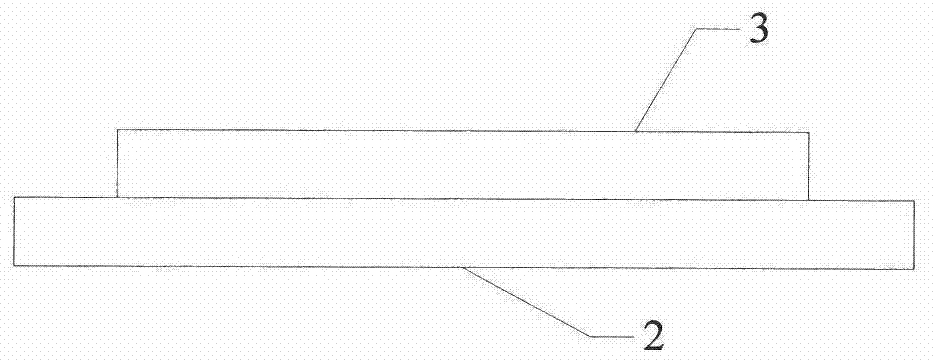
[0030] figure 1 It is a schematic diagram of a surface acoustic wave radio frequency tag. The radio frequency tag includes a surface acoustic wave radio frequency tag chip 3 and a tag antenna 2. The tag antenna 2 is a high temperature and anti-metal antenna. In this embodiment, the material of the tag antenna 2 is dielectric ceramic, and the tag antenna 2 is a microstrip patch antenna. The tag antenna 2 and the surface acoustic wave radio frequency identification chip 3 are welded together by high-temperature solder, and the two can also be welded together by screws.

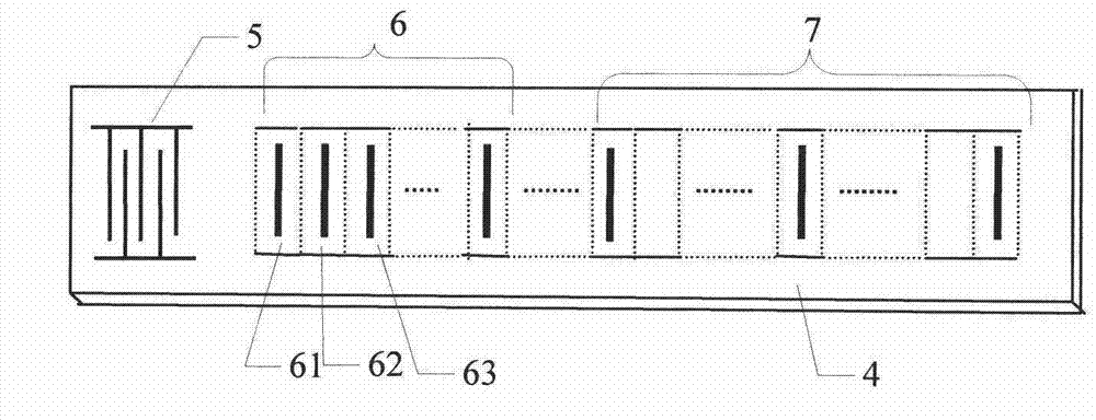
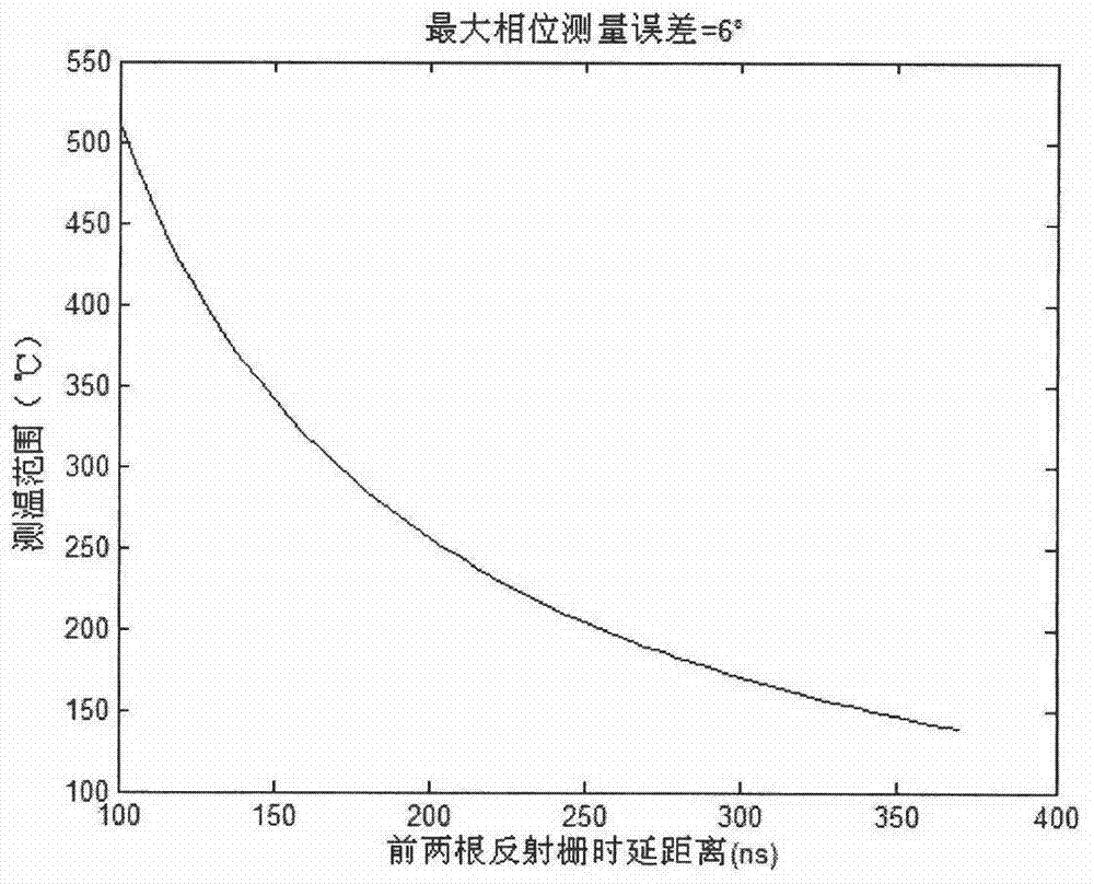
[0031] figure 2 It is a schematic diagram of a surface acoustic wave radio frequency tag chip. The surface acoustic wave radio frequency tag chip 3 in this embodiment is composed of a piezoelectric substrate 4 , an interdigital transducer 5 , a temperature measuring reflection grid 6 and an encoding reflection grid 7 . There are at least three temperature-measuring reflection grids, the distance between the f...


PUM


Abstract

The invention discloses a radio frequency tag capable of measuring temperature and an illuminant lamp with the same. The radio frequency tag capable of measuring temperature comprises an acoustic surface wave radio frequency tag chip and a tag antenna. The acoustic surface wave radio frequency tag chip comprises a piezoelectric substrate, an interdigital transducer and a reflecting grate. The reflecting grate comprises a temperature measuring reflecting grate body and a coding reflecting grate body. The interdigital transducer and the reflecting grate are located on the piezoelectric substrate. The illuminant lamp can be a runway side boundary lamp or a taxiway edge lamp or a runway center line lamp. By the adoption of the radio frequency tag, reliable reading of the radio frequency tag in an inner environment of the illuminant lamp is guaranteed, a special radio frequency tag is integrated with the inner portion of the illuminant lamp, the technology of the internet of things can be actually applied to spot inspection of the illuminant lamp, and efficiency and management efficiency are improved.

Description

technical field [0001] The invention relates to the field of the Internet of Things and radio frequency identification, in particular to a temperature-measurable radio frequency tag used for airport navigation lamps and a navigation lamp equipped with the tag. Background technique [0002] At present, China's aviation, especially the airport construction, is in a period of rapid development. The increasingly strong transportation demand makes the airport have to add more runways, and the flight departures and landings are becoming more and more frequent. The airport navigation aid lighting system is a necessary visual aid to ensure the normal takeoff, landing and taxiing of the aircraft at night, low visibility or other complex weather conditions. According to the relevant regulations of the Civil Aviation Administration of China, it is strictly forbidden for three consecutive navigation lights to be damaged (not lit), otherwise it will be regarded as a serious safety accide...

Claims


Application Information

Patent Timeline
Patent Type & Authority Applications(China)
IPC IPC(8): G06K19/077G06K19/02F21S8/00F21V19/00F21V29/89F21Y101/02F21Y115/10
Inventor 韩韬张晨睿黄辉荣健
Owner SHOULDER ELECTRONICS CO LTD
Learn More