A secondary light distribution lens and equipment for discrete LED light sources

A technology of LED light source and lens, applied in the direction of light source, lighting and heating equipment, semiconductor devices of light-emitting elements, etc., can solve the problem of uneven distribution of light field, which limits the use effect of discrete light source lighting, and can not effectively solve the problem of light spot distribution and influence of light source. Lighting effect and other issues, to achieve the effect of improving light output, excellent spot quality and low cost

Active Publication Date: 2017-12-08
CHENGDU HERCULUX OPTOELECTRONICS TECH CO LTD
View PDF7 Cites 0 Cited by
  • Summary
  • Abstract
  • Description
  • Claims
  • Application Information

AI Technical Summary

Problems solved by technology

The commonality of these two methods is the discrete light source. If it is equipped with a conventional light distribution lens, it will present a spot distribution similar to that of the light source in the illumination light field, resulting in large spot defects, especially at small angles. In the case of high K value requirements, the arrangement of light sources will be obviously distributed in the lighting light field, which greatly affects the lighting effect
In existing applications, there is a method of attaching a small lens array to the end face of the entrance hole. Although this method can homogenize the light field distribution in a part of the high frequency range, it cannot effectively solve the problem that the light spots in the middle and low frequency range are distributed as light sources. Phenomenon, such defects of uneven distribution of light field greatly limit the lighting effect of discrete light sources

Method used


Image

  • A secondary light distribution lens and equipment for discrete LED light sources
  • A secondary light distribution lens and equipment for discrete LED light sources
  • A secondary light distribution lens and equipment for discrete LED light sources

Examples


Embodiment 1

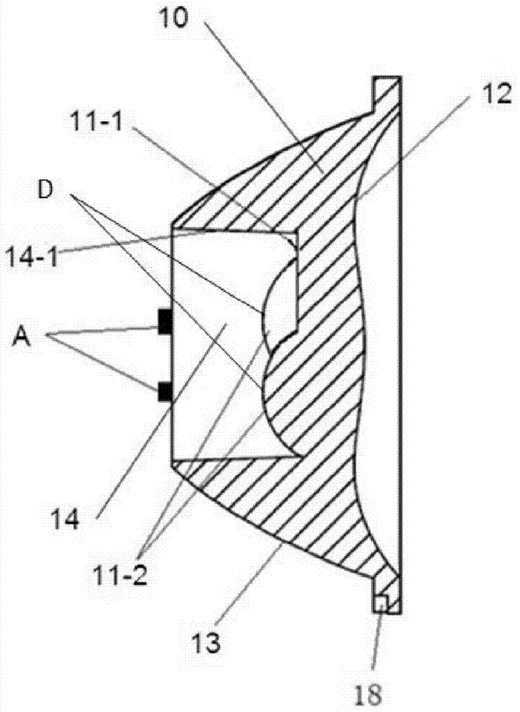
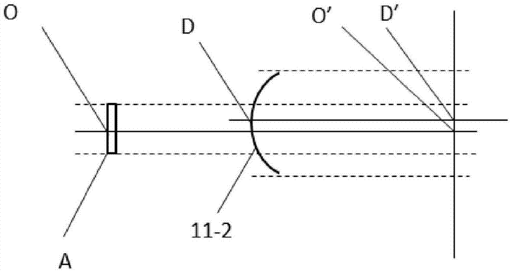
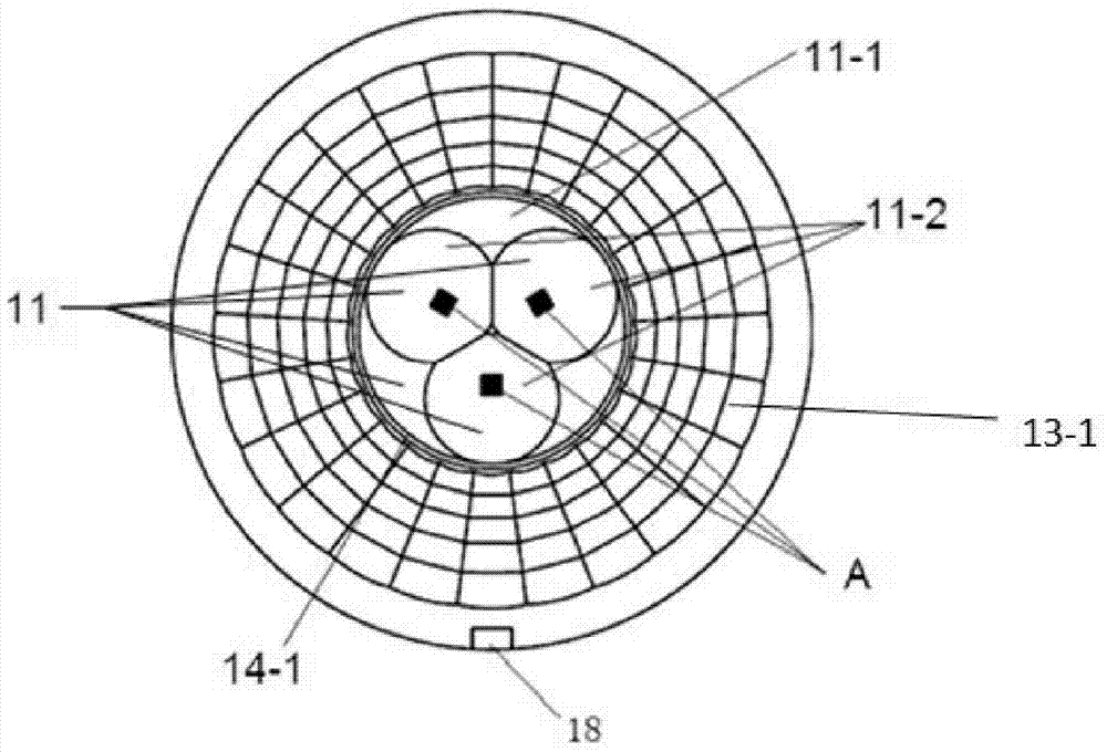
[0052] Such as image 3 As shown, this embodiment includes 3 sub-light sources, of which the 3 sub-light sources are single LED light sources (or LED light sources packaged in a single chip), and the 3 sub-light sources are evenly distributed off-axis relative to the central axis of the lens body. In the implementation, the top end face of the incident hole of the lens is a plane, and on the plane of the top end face, there are sub-incident end faces corresponding to the three sub-light sources, and the sub-incident end faces are spherical; when working, align the three sub-light sources with the corresponding sub-incident end faces The center of the sphere (the off-axis of the three sub-spheres relative to the center axis of rotation on the side of the entrance hole of the lens is the same as the off-axis of the center of the corresponding light source relative to the rotation axis on the side of the entrance hole of the lens). The emitted part of the off-axis light is modula...

Embodiment 2

[0056] Such as Figure 5 As shown, this embodiment includes 3 sub-light source modules, wherein the 3 sub-light source modules respectively include 3 secondary sub-LED light sources arranged in a zigzag shape or 3 single LED light sources packaged in a sub-chip arranged in a zigzag shape ( Figure 4 The small dotted line box indicates the sub-light source module), and the centers of the three sub-light source modules are evenly distributed off-axis relative to the central axis of the lens body. The sub-incidence end faces corresponding to the light source modules are curved surfaces; when working, the center points of the three sub-light source modules are aligned with the centers of the curved surfaces corresponding to the sub-incident end faces, and the corresponding sub-curved surfaces adjust the off-axis of the part emitted by the sub-light source modules. The light is modulated into on-axis light or paraxial light of the axis of the sub-incident end face parallel to the ...


PUM


Abstract

The invention relates to the field of LED light source illumination, and specifically relates to a secondary light distribution lens and a device for a discrete LED light source. A lens incident plane comprises an incident lateral side and an incident end face. The incident end face is a composite plane comprising a main incident end face and a secondary incident end face. The secondary incident end face has a curved face protruding toward the bottom of the lens; and the secondary incident end face is arranged on the main incident end face. The lens is applicable to the discrete LED light source, wherein the secondary incident end face is used corresponding to each secondary light source of the light source. The secondary incident end face converts off-axis lights emitted from the secondary light sources in an off-axis status with respect to the central axis of the lens body into on-axis lights or paraxial lights of the secondary incident end face, accordingly increasing light intensities of lights having small angles. A secondary small convex lens array is densely distributed on the incident end face to uniform the lights, thereby allowing the illumination field of the discrete light source modulated by the lens to reach an ideal effect.

Description

technical field [0001] The invention relates to the field of LED light source lighting, in particular to a secondary light distribution lens and equipment for discrete LED light sources. Background technique [0002] As an energy-saving lighting technology, LED lighting has entered people's lives in an all-round way. In actual production and use, the cost performance of LED lamps has become an increasingly prominent contradiction. Under the same power, the price of an integrated packaged COB light source is several times that of multiple individually packaged light sources, such as the widely used light source packaged in 3030EMC brackets. There is also a COB integrated package light source under the same power, and the light output efficiency of the light source with a large chip arrangement spacing is greater than that of a light source with a small arrangement spacing. Therefore, many lighting manufacturers are now trying to reduce the cost of light sources by using mul...

Claims


Application Information

Patent Timeline
Patent Type & Authority Patents(China)
IPC IPC(8): F21V5/04F21Y115/10
CPCF21V5/04
Inventor 周礼书霍永峰
Owner CHENGDU HERCULUX OPTOELECTRONICS TECH CO LTD
Why Eureka
Try Eureka