Novel multi-wire sawing machine

A wire saw machine, a new type of technology, is applied in the direction of stone processing tools, work accessories, manufacturing tools, etc., which can solve the problems of unstable machining accuracy gear train system, increase the diameter of the driving wheel, and difficulty in ensuring system stability, etc., and achieve reduction Equipment use and maintenance costs, increased synchronization stability, and shortened time spent

Active Publication Date: 2015-07-08
福建天石源科技股份有限公司
View PDF8 Cites 1 Cited by
  • Summary
  • Abstract
  • Description
  • Claims
  • Application Information

AI Technical Summary

Problems solved by technology

[0005] It has the following disadvantages: 1. Since the maximum height of the stone to be cut reaches 2.2 meters and the maximum width reaches 3.6 meters, there are not only two guide wheels up and down on one side of the tensioning wheel, but also a guide wheel at one end of the driving wheel. The diamond beaded rope is stretched into a quadrilateral that can meet the height and width requirements. The more guide wheels, the longer the beaded rope wound on both sides of the column, and the increase in the length of the beaded rope will inevitably lead to an increase in equipment use and maintenance costs;
[0006] 2. During the use of the equipment, the beaded rope needs to be added, replaced and removed from time to time. The specific operation is to wind each wheel one by one manually. When the wheel system contains more wheels, the The more complex and cumbersome the operations that need to be performed, the longer it will take and the higher the cost of equipment use;
[0007] 3. The more gear train components included in the equipment, the more complex the structure will be, and the more errors will accumulate in its manufacturing and installation, the greater the vibration will be when the system is running, and the more difficult it is to guarantee the stability of the entire system. The machining accuracy will also be reduced due to the instability of the gear train system;
[0008] 4. During the operation of the equipment, the beaded rope works under a certain tension. The more wheels it is wound on, the more inflection the beaded rope passes through, which will reduce the service life of the beaded rope. This is because the more inflection, the more fatigue stress will be generated inside the beaded rope. When the fatigue stress accumulates to a certain level, the beaded rope will fail due to fatigue and cannot be used anymore; the reduction of the life of the beaded rope will bring equipment maintenance costs increase
[0009] 5. During the operation of the equipment, the beaded rope works under a certain tension. The tension will be transmitted to the column through the wheels, so that the entire wheel train will generate left and right relative stress on both sides. Columns and beams, the more wheel trains, the greater the stress on the column ( figure 1 The stress on the middle right column is large), when the stress on the columns on both sides is not equal, the wear of the bearings inside the columns on both sides will be inconsistent after a long time of work, which will damage both sides of the equipment It affects the synchronous and smooth operation of the lifting mechanism, which in turn affects the processing accuracy of the equipment
[0010] 6. In order to avoid interference between the diamond beaded rope and the stone, the distance between the guide wheel at the driving end and the guide wheel at the tensioner end needs to accommodate a stone with a width of 3.6 meters. adversely affect the smooth operation of the system
figure 2 is in figure 1 Improvements were made on the basis of reducing the guide wheel at the driving end, increasing the diameter of the driving wheel, and using a large-diameter driving wheel greater than 2.2 meters. The contact between the driving wheel and the diamond beaded rope is more, which is beneficial to the driving wheel and the diamond beaded rope. energy transmission, but it has higher requirements for the driving motor, driving wheel processing, etc. At the same time, the length of the diamond beaded rope between the driving wheel and the other side of the guide wheel has not changed, and the vibration of the diamond beaded rope has not been improved. The force on the side columns is more unequal

Method used


Image

  • Novel multi-wire sawing machine
  • Novel multi-wire sawing machine
  • Novel multi-wire sawing machine

Examples


Embodiment Construction

[0030] The present invention will be described in detail below in conjunction with the drawings, and the following embodiments can enable those skilled in the art to better understand the present invention, but do not limit the present invention in any form.

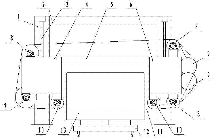
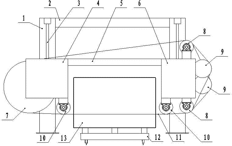
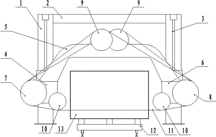
[0031] A new type of multi-wire saw machine is improved on the basis of the existing multi-wire saw machine. Its fixed frame is similar to the prior art, and consists of a column 1, a main beam 2, a vertical lifting device 3, and a driving end frame 4 , frame beam 5, tensioning end frame 6, also has drive wheel 7, guide wheel 8, tension wheel 9, positioning wheel 10, diamond beaded rope 11, block car 12, stone 13 is fixed on the block car 12, the main changes are: the tensioning wheel 9 is fixed on the top of the frame beam 5, and is located between the columns 1 on both sides (not necessarily the middle part), the driving wheel 7 and the guide wheel 8 are fixed on the side of the column 1 on both sides, and the two sides...


PUM


Abstract

A novel multi-wire sawing machine comprises stand columns, a main cross beam, vertical lifting devices, a drive end rack, a rack cross beam, a tensioning end rack, a driving wheel, guiding wheels, tensioning wheels, two locating wheels, diamond string bead wires and a quarry stone vehicle. The novel multi-wire sawing machine is characterized in that the tensioning wheels are fixed on the rack cross beam and located between the stand columns on the two sides, the driving wheel and the guiding wheels are fixed on the edges of the stand columns on the two sides, and the locating wheels are symmetrically fixed at the two sides of the quarry stone vehicle. According to the novel multi-wire sawing machine, the guiding wheel number is decreased, the cost is lowered, the operation is simplified, the structure is compact, the service life of the string bead wires is prolonged, the stand columns on the two sides are stressed evenly, and the operational stationarity of an overall wheel train system is improved. The novel multi-wire sawing machine has the advantages of being reasonable in stress, simple in structure, high in machining accuracy, stable in work, low in maintenance cost and the like.

Description

technical field [0001] The patent belongs to the field of stone plate processing equipment and relates to a multi-wire saw equipment for stone plate cutting. Background technique [0002] When processing large slabs (height ≥ 1.5 meters, length ≥ 2 meters), the multi-wire saw machine has high efficiency, simple equipment operation, low production cost, high stone utilization rate, and environmental protection compared with traditional sand saws and circular saws. Advantages such as less pollution. The multi-wire saw machine represents the development trend of stone slab cutting. [0003] Existing multi-wire saw machines, such as figure 1 The shown includes column 1, main beam 2, vertical lifting device 3, driving end frame 4, frame beam 5, tensioning end frame 6, driving wheel 7, the driving end has one guide wheel, and the tensioning end has two Guide wheel 8, two sets of tensioning wheels 9, two positioning wheels 10, diamond beaded rope 11, block car 12, stone 13 is fi...

Claims


Application Information

Patent Timeline
Patent Type & Authority Applications(China)
IPC IPC(8): B28D1/08B28D7/00
CPCB28D1/08B28D7/00
Inventor 朱文志林孝狮刘庆峰陈世春陈礼干
Owner 福建天石源科技股份有限公司
Why Eureka
Try Eureka