Dual power rotation deep inclined hole drill machine and processing method thereof

A dual-power, rotating direction technology, used in boring/drilling, metal processing equipment, drilling/drilling equipment, etc. The position is accurate, the precision is high, and the work efficiency is improved.

Inactive Publication Date: 2015-07-08
玉环制冷设备配件有限公司
View PDF7 Cites 6 Cited by
  • Summary
  • Abstract
  • Description
  • Claims
  • Application Information

AI Technical Summary

Problems solved by technology

[0003] The traditional method of drilling inclined holes is mainly to reverse the crankshaft and fix it with an inclination of 2 degrees, and use the drill bit in the drilling power head to enter from the upper bottom surface of part B until the drill bit enters part A, resulting in the drill bit being easy to deflect during processing. In turn, the position of the drilled hole is inaccurate and the accuracy is low
[0004] At the same time, in the process of processing, because the diameter of part A is about 11mm, the diameter of the upper bottom surface of part B is 8mm, and the diameter of the lower bottom surface is 11mm, and the center of the deep inclined hole deviates from the center of the upper bottom surface by nearly 0.5mm. The eccentric direction of the inclined hole is the same as the inclined direction of the deep inclined hole, so that the deeper the drill bit penetrates into the long axis, the thinner the wall thickness between the deepest part of the deep inclined hole and the outer surface of the long axis, and the drill bit keeps rotating at high speed, resulting in In the process of drilling deep inclined holes, the long axis of the crankshaft is easily broken by the drill bit and damaged, resulting in high scrap rate and low resource utilization
[0005] Finally, the traditional method of drilling inclined holes can only process one workpiece at a time, and the work efficiency is low

Method used


Image

  • Dual power rotation deep inclined hole drill machine and processing method thereof
  • Dual power rotation deep inclined hole drill machine and processing method thereof
  • Dual power rotation deep inclined hole drill machine and processing method thereof

Examples


Embodiment Construction

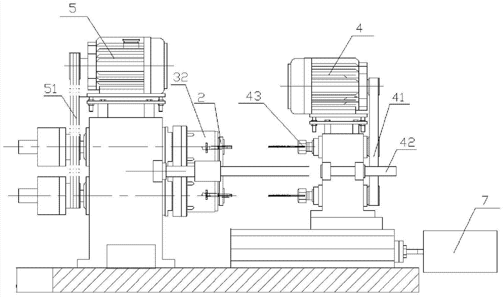
[0030] refer to Figure 1-Figure 8 To further illustrate the present invention, the following examples are used to illustrate the present invention, but are not intended to limit the scope of the present invention.

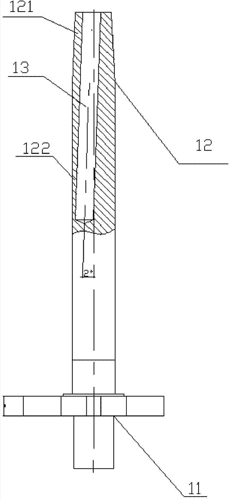
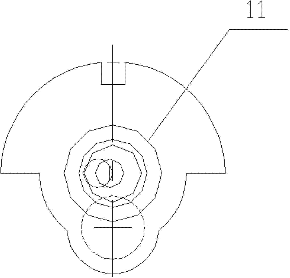
[0031] refer to Figure 2-Figure 3 : the workpiece to be processed includes a centrifugal part 11 and a major axis 12, and the major axis 12 includes a cylindrical A part 121 and a conical B part 122 connected to the A part 121, and in the processing process, it is necessary to drill the major axis 12 Get a deep inclined hole 13 that passes through the B portion 122 and partially penetrates into the A portion 121. The centerline of the deep inclined hole 13 intersects with the centerline of the major axis 12, and the formed acute angle is 2 degrees. At the same time, the deep inclined hole The hole center of 13 deviates nearly 0.5 mm from the center of the upper bottom surface of B part 122, the diameter of A part 121 is about 11 mm, the diameter of the upper bot...


PUM


Abstract

The invention relates to the technical field of deep inclined hole drilling, in particular to a dual power rotation deep inclined hole drill machine. The dual power rotation deep inclined hole drill machine comprises a drilling device connected with a drill bit, a first drive device which drives the drilling device to perform reciprocating motion and drill a deep inclined hole for a work piece, a clamp used to fix the work piece, at least one group of clamping devices capable of clamping the clamp and a second drive device which drives the clamping devices to rotate, wherein the central line of the drill bit, the central line of the clamp and the central line of the deep inclined hole are located on the same straight line, and the rotation direction of the drill bit is opposite to the rotation direction of the clamp. The dual power rotation deep inclined hole drill machine is simple in structure and strong in practicability.

Description

technical field [0001] The invention relates to the technical field of inclined hole drilling, in particular to a dual-power rotary deep inclined hole drilling machine and a processing method thereof. Background technique [0002] The crankshaft is the main rotating part of the engine. After the connecting rod is installed, it can undertake the up and down (reciprocating) motion of the connecting rod and change it into a circular (rotating) motion. It is an important part of the engine. Its material is made of carbon structural steel or ductile iron. The rotation of the crankshaft is the power source of the engine. It is also the source of power for the entire mechanical system. The crankshaft includes a crank and a long shaft. The long shaft includes a cylindrical part A and a conical part B connected to part A. During processing, it is necessary to drill a through B for the long shaft. part and part of the deep inclined hole in part A, the diameter of the deep inclined ho...

Claims


Application Information

Patent Timeline
Patent Type & Authority Applications(China)
IPC IPC(8): B23B41/02B23B39/16
CPCB23B41/02B23B39/162
Inventor 叶继安叶建国金作庆李勇
Owner 玉环制冷设备配件有限公司
Why Eureka
Try Eureka