Hot-upset mold

A mold and hot upsetting technology, which is applied in the manufacture of tools, forging/pressing/hammer devices, forging/pressing/hammering machines, etc., can solve problems such as increased production costs, inability to guarantee process size requirements, and poor end precision. , to achieve the effect of saving time, simple structure and convenient operation

Inactive Publication Date: 2015-07-08
HUBEI XINGYUAN SCI & TECH
View PDF0 Cites 1 Cited by
  • Summary
  • Abstract
  • Description
  • Claims
  • Application Information

AI Technical Summary

Problems solved by technology

[0002] The existing hot upsetting mold structure can only upsetting the boss with a circular end, and cannot heat out hexagonal or flat square bosses.
Moreover, the precision of the end of the upsetting is poor, and the processing size requirements cannot be guaranteed, and turning processing is required
increased production costs

Method used


Image

  • Hot-upset mold
  • Hot-upset mold

Examples


Embodiment Construction

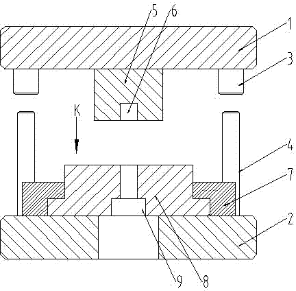
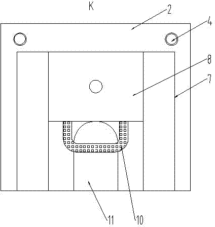
[0009] Such as figure 1 with figure 2 As shown, a hot upsetting mold includes an upper template 1 and a lower template 2. The upper template 1 and the lower template 2 are guided by a guide sleeve 3 and a guide column 4. The upper mold 5 is fixed on the upper template 1 by bolts. , the end of the upper die 5 is provided with a blind hole 6 for positioning the bar, which can contain the upper end of the bar to prevent deformation of the upper end of the bar during upsetting. A slideway 7 is fixed on the lower template 2, and the lower die 8 and The slideway 7 is guided and connected, and the lower mold 8 is provided with a cavity 9; the lower mold 8 is provided with a push-pull handle 10, and the lower template 2 is provided with a material return gap 11. The final workpiece can fall from the material return gap 11; the lower mold 8 and the lower template 2 form a closed cavity during work to ensure that the metal is completely filled according to the shape of the cavity, so ...


PUM


Abstract

The invention discloses a hot-upset mold. The hot-upset mold comprises an upper template and a lower template, wherein the upper template and the lower template are guided through a guide sleeve and a guide column component; an upper mold is fixed on the upper template; a blind hole for positioning a rod material is formed in the end part of the upper mold; a slide way is fixed on the lower template; a lower mold is in guide connection with the slide way; a molding cavity is formed in the lower mold; a push-pull handle is arranged on the lower mold; a material return opening is formed in the lower template; when the lower mold is located in a pull-out state, a hot-upset workpiece can drop down from the material return opening; the lower mold and the lower template are formed to the closed molding cavity to guarantee the filling of metal totally according to the appearance of the molding cavity, so that the purpose of upsetting different shapes at the end part of the rod material is achieved; the hot-upset mold is simple in structure and convenient to operate, saves the time, can realize the requirements of machining different shapes at the end part of the rod material, and reduces the manufacturing cost.

Description

technical field [0001] The invention relates to a hot pressing die, in particular to a hot upsetting die for the end of a bar. Background technique [0002] The existing hot upsetting die structure can only upset bosses with circular ends, but cannot heat out hexagonal or flat square bosses. Moreover, the precision of the end part produced by upsetting is poor, and the processing size requirements cannot be guaranteed, and further turning processing is required. Increased production costs. Contents of the invention [0003] The invention provides a hot upsetting die, which aims at meeting the requirements of different shapes and sizes. [0004] In order to solve the above technical problems, the technical solution of the present invention is: a hot upsetting mold, including an upper template and a lower template, the upper template and the lower template are guided by a guide sleeve and a guide column assembly, and the upper mold is fixed on the upper template , the end...

Claims


Application Information

Patent Timeline
IPC IPC(8): B21J13/02
CPCB21J13/02
Inventor 冀元贵谢登山
Owner HUBEI XINGYUAN SCI & TECH
Why Eureka
Try Eureka