Single-live-wire switch

A single live wire switch and resistor technology, applied in lighting devices, light sources, electric light sources, etc., can solve the problems of standby circuit inoperability, unstable load current, expensive metal wires, etc., achieve low power consumption, ensure stable operation, and affect small effect

Inactive Publication Date: 2015-07-01
成都思唯奇科技有限公司
View PDF5 Cites 1 Cited by
  • Summary
  • Abstract
  • Description
  • Claims
  • Application Information

AI Technical Summary

Problems solved by technology

Since ordinary households at home and abroad are mostly wired with single live wires, according to the traditional method, if you want to use a switch that itself needs power supply, you need to rewire. increase, so there is an urgent need for a single live wire power switch to solve the wiring problem
Since the standby power of the single live wire switch is powered by the current flowing through the load to the control circuit of the switch, the switch itself needs to consume a certain amount of current. If the standby input current is small, the standby circuit will not work. If the standby input current is large, the standby circuit will not work. Will cause load current instability

Method used


Image

  • Single-live-wire switch

Examples


Embodiment Construction

[0011] In order to make the purpose, technical solution and advantages of the present application clearer, the present application will be further described in detail below in conjunction with the accompanying drawings and specific embodiments.

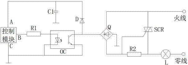
[0012] Such as figure 1 A single live wire switch shown is characterized in that it includes a rectifier bridge Q, an optocoupler OC, a diode D, a capacitor C1, a bidirectional thyristor SCR, a first resistor R1, a second resistor R2, and a control module, the rectifier The bridge Q is connected in series with the second resistor R2 and the load L in turn, and then connected to the alternating current. One end of the other two terminals of the rectifier bridge Q is grounded, and the other end is connected to the positive pole of the diode D and the output terminal of the optocoupler OC. The negative poles of the diode D are respectively Connect the input end A of the control module to one end of the capacitor C1, the other end of the ...


PUM


Abstract

The invention relates to a single-live-wire switch. The single-live-wire switch is characterized by comprising a rectifier bridge, an optical coupler, a diode, a capacitor, a bidirectional silicon controlled rectifier, a first resistor, a second resistor and a control module; the rectifier bridge is connected to an alternating current after being sequentially connected with the second resistor and a load in series; one connection end of the rectifier bridge is grounded, and the other connection end of the rectifier bridge is connected with a positive electrode of the diode and the output end of the optical coupler; a negative electrode of the diode is connected with the input end of the control module and one end of the capacitor; the other end of the capacitor is grounded; the output end of the control module is connected with the first resistor; the other end of the first resistor is connected with the input end of the optical coupler; the other two ends of the optical coupler are grounded; one end of the bidirectional silicon controlled rectifier is connected with a live wire, and a control electrode and the other end of the bidirectional silicon controlled rectifier are connected with two ends of the second resistor respectively. The single-live-wire switch has the advantages that a single-live-wire electricity supply circuit is used for powering the switch, the wiring problem is solved, the whole circuit is low in power consumption, influences on the load are small, and stable operation of the load is guaranteed.

Description

technical field [0001] The invention relates to the technical field of home appliance switches, in particular to a single live wire switch. Background technique [0002] In order to make the switch control of home lighting and electrical appliances intelligent, single live wire switches gradually replace traditional mechanical wall switches. Since ordinary households at home and abroad are mostly wired with single live wires, according to the traditional method, if you want to use a switch that itself needs power supply, you need to rewire. increase, so there is an urgent need for a single live wire power-taking switch to solve the wiring problem. Since the standby power of the single live wire switch is powered by the current flowing through the load to the control circuit of the switch, the switch itself needs to consume a certain amount of current. If the standby input current is small, the standby circuit will not work. If the standby input current is large, the standby...

Claims


Application Information

Patent Timeline
Patent Type & Authority Applications(China)
IPC IPC(8): H05B37/02
Inventor 廖望
Owner 成都思唯奇科技有限公司
Why Eureka
Try Eureka