
Overlay structure, input device and method for manufacturing the overlay structure

A technology of covering structure and input device, applied in the direction of user/computer interaction input/output, electrical components, electrical switches, etc., can solve the problems of increased manufacturing cost, time-consuming process, complicated procedures, etc., to achieve the best pressing feel, The effect of solving the problem of alignment accuracy

Active Publication Date: 2018-10-02
CHICONY ELECTRONICS
View PDF7 Cites 0 Cited by
  • Summary
  • Abstract
  • Description
  • Claims
  • Application Information

AI Technical Summary

Problems solved by technology

However, the pressing feeling provided by the pressing spacer is not only still not comparable to that of the traditional keyboard, but also must face the problem of alignment accuracy when the pressing spacer is arranged on the cover layer, so its manufacturing cost will also be affected by the additional pressing spacer. piece by piece
[0004] In addition, in the manufacturing process of the existing pressing pads, the glue needs to be injected into the mold to form the shape of the corresponding button. After the glue is hardened and formed, it is then adhered to the sheet body. The overall process is time-consuming and complicated.

Method used


Image

  • Overlay structure, input device and method for manufacturing the overlay structure
  • Overlay structure, input device and method for manufacturing the overlay structure
  • Overlay structure, input device and method for manufacturing the overlay structure

Examples


Embodiment Construction

[0030] Hereinafter, several embodiments of the present invention will be disclosed with the accompanying drawings. For clear description, many specific details will be described in the following description. However, it should be understood that these specific details should not be used to limit the present invention. That is to say, in some embodiments of the present invention, these specific details are unnecessary. In addition, for the sake of simplification of the drawings, some conventional structures and elements will be shown in a simple schematic manner in the drawings.

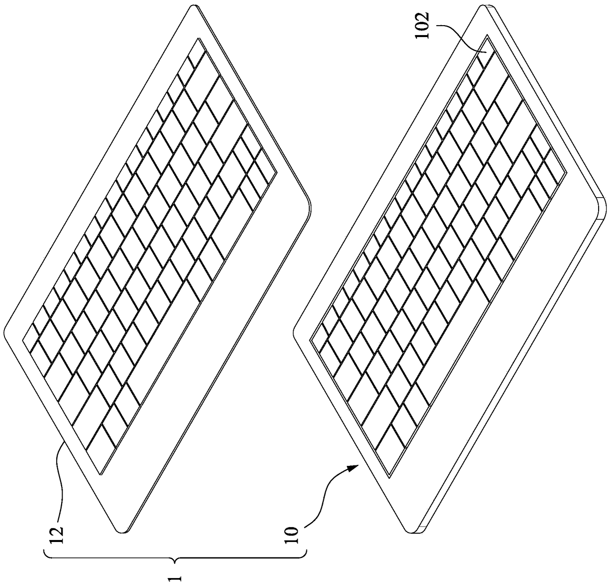
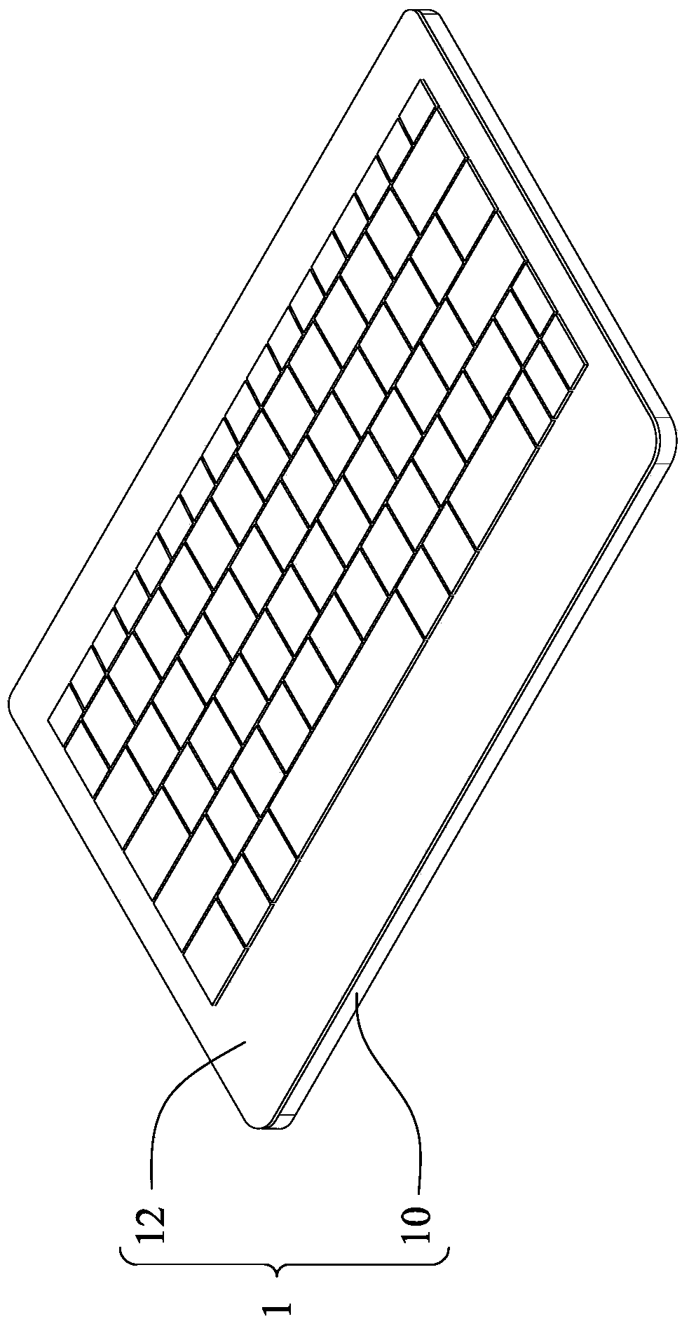
[0031] Please refer to Figure 1A , Figure 1B as well as figure 2 . Figure 1A It is an exploded perspective view of the input device 1 according to an embodiment of the present invention. Figure 1B for Figure 1A A perspective view of the input device 1 in. figure 2 for Figure 1A A cross-sectional view of the covering structure 12 in.

[0032] Such as Figure 1A to Figure 2 As shown, in this embodiment,...


PUM


Abstract

The invention discloses an overlay structure which comprises a bottom coating layer, a top coating layer and a thermoplastic material layer. The thermoplastic material layer is overlapped between the bottom coating layer and the top coating layer. The thermoplastic material layer comprises first thermoplastic material layer portions and second thermoplastic material layer portions which are connected with one another. The first thermoplastic material layer portions have first thicknesses. The second thermoplastic material layer portions have second thicknesses. The first thicknesses are larger than the thickness of the top coating layer. Each first thickness is 4-7 times each second thickness. The invention further discloses an input device with the overlay structure and a method for manufacturing the overlay structure.

Description

Technical field [0001] The invention relates to a covering structure, an input device applying the covering structure, and a manufacturing method of the covering structure. Background technique [0002] Although tablet computers have become more and more popular in recent years, in terms of current personal computer usage habits, keyboards (or mice) are still important input devices for inputting text, symbols or numbers. Therefore, at present, some industry players have introduced a thin touch keyboard specifically for tablet computers, which can be used as a protective cover for tablet computers. In order to achieve a thin appearance, the touch keyboard uses a Force Sensitive Resistor (FSR) as a component for sensing the input signal, and a covering layer is coated on its surface for the user's finger to touch. [0003] However, the touch keyboard cannot provide a user with a pressing feel similar to that provided by a traditional keyboard. Therefore, the user cannot clearly kno...

Claims


Application Information

Patent Timeline
Patent Type & Authority Patents(China)
IPC IPC(8): G06F3/02H01H13/705
Inventor 陈以恒林中尧林毓修
Owner CHICONY ELECTRONICS
Learn More