
Light guide plate for illumination and illuminating lamp

A light guide plate and light-emitting surface technology, which is applied to the light guide, lighting device, lighting and heating equipment of the lighting system, etc., can solve the problems of poor transfer rate, uneven distribution, poor front luminance of the light-emitting plate of the light guide plate, etc. Achieve the effect of improving the transfer rate, uniform lighting light, and improving uniformity

Inactive Publication Date: 2015-07-01
CHI MEI CORP
View PDF4 Cites 3 Cited by
  • Summary
  • Abstract
  • Description
  • Claims
  • Application Information

AI Technical Summary

Problems solved by technology

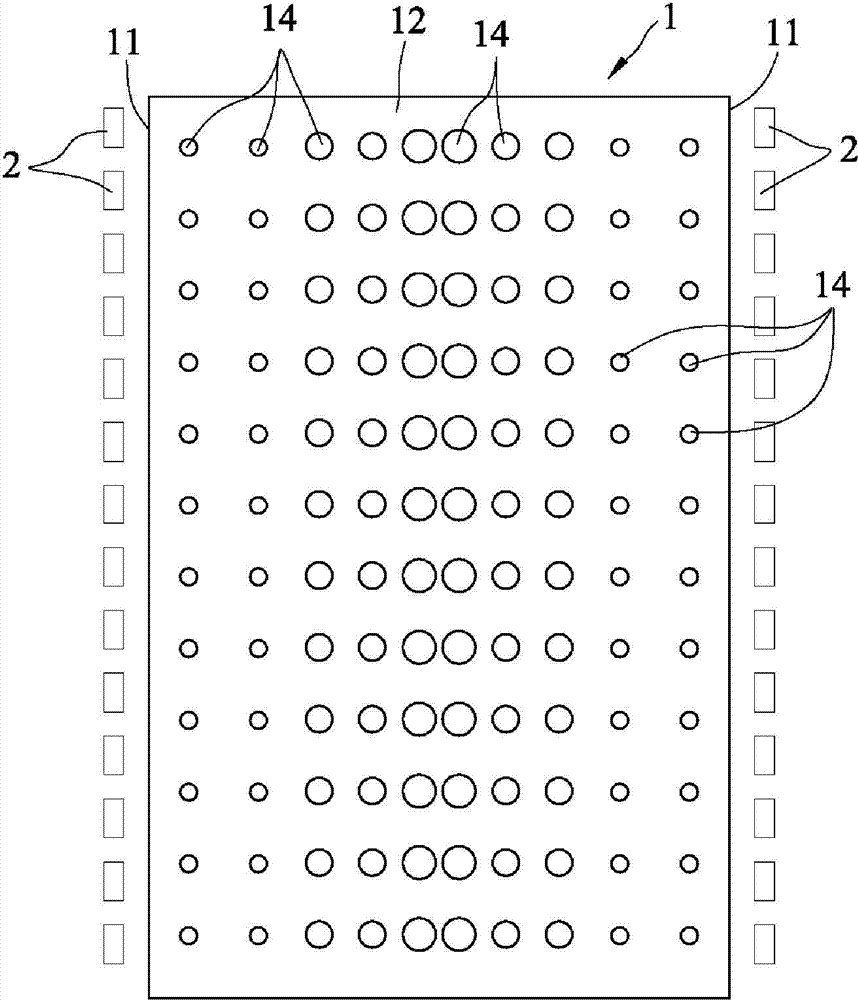
[0004] In addition, there is a light-emitting diode (LED) light guide plate, which uses a transfer roller to form a hemispherical microstructure on the inner surface of the light guide plate. The distribution density design of the hemispherical microstructure is roughly the same as figure 1 , figure 2 The printed structure 14 is similar to the printed structure 14, which is also designed to achieve uniform light guide. However, the disadvantage of the hemispherical microstructure is that the transfer rate formed by the microstructure is not good, so that the front luminance of the light from the light guide plate is poor.
[0005] In order to solve the above-mentioned problems of the printed light guide plate or the light guide plate with hemispherical microstructures, the light guide effect and the uniformity of the light output are not good, and to solve the printed structure 14 or the hemispherical microstructure distribution density and structural size change design Complicated, poor transfer rate and other shortcomings, so it is urgent to find a solution

Method used


Image

  • Light guide plate for illumination and illuminating lamp
  • Light guide plate for illumination and illuminating lamp
  • Light guide plate for illumination and illuminating lamp

Examples


Embodiment Construction

[0036] The present invention will be described in detail below with reference to the accompanying drawings and embodiments. It should be noted that in the following description, similar elements are denoted by the same numerals.

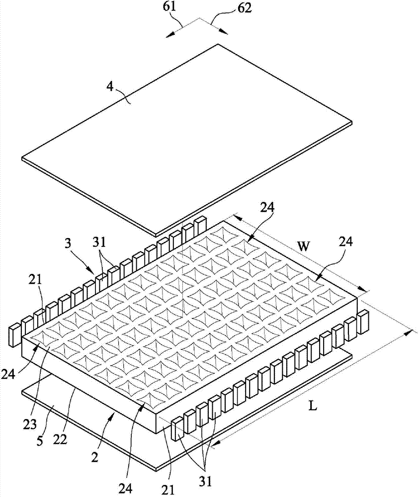
[0037] refer to Figure 3 to Figure 6 , A first preferred embodiment of the lighting fixture of the present invention includes: a light guide plate 2 for lighting, a light emitting unit 3 , a reflecting plate 4 and a diffusing plate 5 . In this embodiment, the lighting direction of the lighting fixture is downward, but the implementation is not limited to this, and it can be changed depending on the application occasion and installation location.

[0038] The light guide plate 2 for illumination comprises: two light-incident surfaces 21 spaced left and right and opposite to each other, a light-exit surface 22 and an inner surface 23 connected between the light-incident surfaces 21 and opposite to each other, and a plurality of the same size and The ...


PUM


Abstract

A light guide plate for illumination and an illuminating lamp are provided. The light guide plate for illumination comprises emitting and inner surfaces opposite to each other, at least an incident surface connected to the emitting and inner surfaces, and a plurality of concaved microstructures distributed in the inner surface. The cross section of each of the concaved microstructures has a shape of a quadrangle with four curves. Each of the concaved microstructures has an opening disposed at the inner surface. Through the design of the structure of the four curves for each of the concaved structure, the innovative structure can achieve uniform light guiding so as to permit uniform illumination of the illuminating lamp.

Description

technical field [0001] The invention relates to a light guide plate and a lamp, in particular to a light guide plate for illumination with a plurality of concave microstructures and an illumination lamp including the light guide plate for illumination. Background technique [0002] Side-lit light-emitting diode (LED) light guide plates have developed into an important component of lighting fixtures. With the continuous promotion of lighting applications, the market's requirements for light-emitting diode light guide plates are becoming more and more stringent, especially in large and medium-sized lighting guides. The performance of the light panel (such as light uniformity, etc.) must meet market requirements. refer to figure 1 , figure 2 , showing some components of a known lighting fixture, mainly including a light guide plate 1 and a plurality of light emitting elements 2 respectively arranged on the left and right sides of the light guide plate 1 . The light guide pl...

Claims


Application Information

Patent Timeline
Patent Type & Authority Applications(China)
IPC IPC(8): F21V8/00F21V13/12F21Y101/02F21Y115/10
CPCG02B6/0043
Inventor 陈信宏郭俊良萧琇方蔡爵仰
Owner CHI MEI CORP
Learn More