
Hydraulic oil cylinder

A technology of hydraulic oil cylinder and cylinder barrel is applied in the field of hydraulic oil cylinder, which can solve the problems of seal damage and oil cylinder failure, and achieve the effect of remarkable dynamic sealing effect.

Inactive Publication Date: 2015-07-01
施周平
View PDF4 Cites 6 Cited by
  • Summary
  • Abstract
  • Description
  • Claims
  • Application Information

AI Technical Summary

Problems solved by technology

This pressure sometimes reaches a high level, and even the seal is squeezed out of the seal installation groove, causing the seal to be damaged and eventually causing the cylinder to fail.

Method used


Image

  • Hydraulic oil cylinder

Examples


Embodiment Construction

[0015] The present invention will now be further described in conjunction with specific examples, and the following examples are intended to illustrate the present invention rather than further limit the present invention.

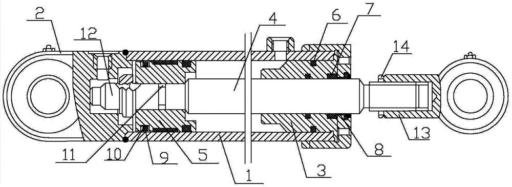
[0016] Such as figure 1 Shown, a kind of hydraulic oil cylinder, this hydraulic oil cylinder comprises cylinder barrel 1, cylinder bottom 1, guide sleeve 3, piston rod 4 and piston 5, is provided with first sealing ring 6 between guide sleeve 3 and cylinder barrel 1, piston rod There is a first dynamic sealing structure between 4 and the guide sleeve 3, and the first dynamic sealing structure includes an "O"-shaped elastic body 7 and a "Y" behind it. X ”-shaped seal ring 8, a seal installation groove is provided between the piston 5 and the cylinder 1, a second seal ring 9 and a baffle 10 are arranged in the installation groove, and a through hole is provided on the baffle 10.

[0017] The first dynamic sealing structure includes an "O" shaped elastic bod...


PUM


Abstract

The invention relates to engineering machinery common equipment, in particular to a hydraulic oil cylinder. The hydraulic oil cylinder comprises a cylinder barrel, a cylinder bottom, a guide sleeve, a piston rod and a piston, wherein a first seal ring is arranged between the guide sleeve and the cylinder barrel, a first movable seal structure is arranged between the piston rod and the guide sleeve, the first movable seal structure comprises an O-shaped elastomer and a YX-shaped seal ring located behind the O-shaped elastomer, a sealing piece installing groove is formed between the piston and the cylinder barrel, the installing groove is internally provided with a second seal ring and a baffle, and a through hole is formed in the baffle. According to the hydraulic oil cylinder, the first movable sealing structure comprises the O-shaped elastomer and the YX-shaped seal ring located behind the O-shaped elastomer, the seal effect between the piston rod and the guide sleeve is more evident, fluid is easy to flow out by the arrangement of the through hole formed in the baffle of the second seal ring, and the phenomenon that the sealing piece is squeezed out from the installing groove caused by fluid accumulation is prevented.

Description

technical field [0001] The invention relates to equipment commonly used in engineering machinery, in particular to a hydraulic oil cylinder. Background technique [0002] The hydraulic cylinder is the key executive element in the hydraulic system or equipment. Its sealing performance directly affects the reliability of the entire system. Therefore, its sealing performance, especially the dynamic seal between the piston rod and the guide sleeve, has always been the top priority in the hydraulic industry at home and abroad. research topic. Cylinder seal includes reciprocating motion seal between piston and cylinder, piston rod and guide sleeve, and static seal of each matching part. The "O" ring is used as a static seal. Due to the simple structure of the seal, it is easy to install and the groove size has been standardized. Therefore, it is no longer a problem to use the "O" seal as a static seal. Therefore, it is no longer a problem to use the "O" seal as a static seal. ...

Claims


Application Information

Patent Timeline
Patent Type & Authority Applications(China)
IPC IPC(8): F15B15/14F15B15/20
CPCF15B15/1461
Inventor 施周平
Owner 施周平
Learn More