Plate material omnibearing locating structure and method in hot press forming technology

A technology of hot-pressing forming and positioning method, which is applied in positioning devices, manufacturing tools, metal processing equipment, etc., can solve the problems of inability to locate in four directions, instability, and damage to the surface of the forming block, so as to achieve accurate and convenient positioning and not easy to deform. wear effect

Inactive Publication Date: 2015-07-01
上海凌云汽车模具有限公司
View PDF6 Cites 1 Cited by
  • Summary
  • Abstract
  • Description
  • Claims
  • Application Information

AI Technical Summary

Problems solved by technology

The problem with this method is that it does not take into account the instability in the production process of the parts. In the production process of the parts, it is inevitable that there will be small changes in the size of the hot-pressed parts due to the wear of the mold or the change of the production environment. In the subsequent process of laser cutting / punching and checking tool inspection, the quality of the produced parts will be unstable due to the instability of the secondary clamping and positioning
The problem with this method is that in the process of using the ball stud to form the spherical convex hull, the ball stud is very easy to wear and cause the size of the spherical convex hull to change, and the spherical convex hull is prone to defects such as cracking and necking during the molding process , when the cracking is more serious, the material may fall off and become waste, which will cause great harm to the surface of the molding block of the mold; no matter what the above reasons cause the change in the size of the spherical convex hull, it will cause a second step in the subsequent process. Instability of clamping and positioning
This method is similar to the second method, but in this method, the V-shaped convex hull with a straight-line tip processed by the V-shaped breaking knife in the hot-pressed part can only be used in the secondary clamping process of the hot-pressed part The main positioning in a certain direction cannot be used as a 4-direction positioning, and the positioning accuracy and practicability are low

Method used


Image

  • Plate material omnibearing locating structure and method in hot press forming technology
  • Plate material omnibearing locating structure and method in hot press forming technology
  • Plate material omnibearing locating structure and method in hot press forming technology

Examples


Embodiment approach 1

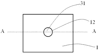
[0029] This embodiment provides an all-round positioning structure and its all-round positioning method for sheet metal in the hot pressing forming process, such as figure 1 and 2 As shown, the above-mentioned all-round positioning structure is a raised circular flange hole extending from the plane of the sheet material 1. The circular flange hole and the sheet material 1 are integrally structured. The end 111 is higher than the blank 1 by a certain distance.

[0030] In this embodiment, before forming the above-mentioned circular flanging hole, firstly a circular pre-punching hole 12 will be processed at a preset position on the sheet material 1, and then the The flanging pin 3 processes the circular pre-punching hole 12 into the above-mentioned circular flanging hole, as figure 2 As shown, it can be seen that the side of the circular flanging hole is a vertical edge 13 of an overall structure, and the above-mentioned circular flanging hole can be used as the main positio...

Embodiment approach 2

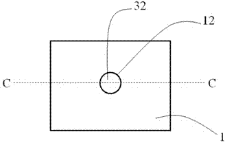
[0038] This embodiment is a further improvement of Embodiment 1. The main improvement is that in Embodiment 1, a flanged pin 3 with a spherical pin head 31 is used, and a circle with a vertical edge 13 of an integral structure is formed. Shaped flanging hole, because the contact area between the limit inner side of this circular flanging hole and the flanging pin 3 is larger, so it is not easy to unload the flanging pin 3; The flanging pin 3 of head 32, the circular flanging hole that has the inclined edge 14 of integral structure that molding goes out, because the frictional force between the inclined edge 14 inner side of integral structure and flat head tapered pin head 32 is less, so can Use less force to remove the flange pin 3, such as image 3 and 4 shown.

[0039] Apart from this, this embodiment is completely the same as Embodiment 1, and will not be repeated here.

Embodiment approach 3

[0041]This embodiment is a further improvement of Embodiment 1. The main improvement is that the side of the circular flanged hole in Embodiment 1 is the vertical edge 13 of the overall structure. There is a defect in this circular flanged hole: when needed When the flanging pin 3 is removed, because the inner wall of the vertical edge 13 of the overall structure of the circular flanging hole is close to the pin body 33 of the flanging pin 3, the frictional force between the two is relatively large, and the flanging pin 3 It is not easy to remove; and the edge of the circular flanging hole in this embodiment is the vertical edge 114 of the multi-lobed structure (or zigzag structure, wave-shaped structure, etc.), of course, if the corresponding pre-punched hole is multi-lobed (or zigzag structure, wavy structure, etc.) pre-punching hole 17, the contact area between the inner wall of the vertical side 15 of the multi-lobe structure and the flanging pin 3 is reduced, and the frict...


PUM


Abstract

The invention relates to the field of hot press forming and discloses a plate material omnibearing locating structure and method in a hot press forming technology. According to the omnibearing locating structure, a circular flanged hole extending out from the surface of a plate material (1) and integrated with the plate material (1), and the edge (11) of the circular flanged hole is higher than the plane where the plate material (1) is placed. When locating is needed, a pre-punched hole (12) is machined in a preset position of the plate material (1), then the pre-punched hole (12) is machined into the circular flanged hole, and then a locating pin (2) is inserted into the circular flanged hole to carry out omnibearing locating on the plate material (1). The circular flanged hole is a protruding hole relative to the plane of the plate material, so that when the plate material is located, only the locating pin with the same size and shape as the hole needs to be used, omnibearing locating can be carried out, the circular flanged hole cannot deform and be abraded easily, and locating is accurate.

Description

technical field [0001] The invention relates to the field of hot pressing forming, in particular to an omnidirectional positioning structure and positioning method for sheet materials in the hot pressing forming process. Background technique [0002] In the production process of thermoformed parts, the flat material is first punched into the required shape in the thermocompression die, and then the required product part edge contour and vacancy are obtained in the subsequent laser cutting / trimming die, so this time produces The requirements for the secondary clamping and positioning of hot-pressed parts are met. Moreover, during the inspection process of the hot-pressed parts stamped out by the hot-pressing die, the requirement for clamping and positioning of the hot-pressed parts on the inspection tool also arises. [0003] For clamping and positioning, there are usually three methods in the prior art. One method is to use only the shape of the part itself as the positioni...

Claims


Application Information

Patent Timeline
Patent Type & Authority Applications(China)
IPC IPC(8): B21D43/00
CPCB21D43/003
Inventor 徐士昌辛宪秀
Owner 上海凌云汽车模具有限公司
Why Eureka
Try Eureka