Working roller bending device for double-roller rolling machine and roller bending force control method

A work roll bending and four-high rolling mill technology, applied in metal rolling, profile control, metal rolling, etc., can solve problems such as cylinder size and valve capacity waste, and achieve fewer cylinders, fewer maintenance points, and avoidance of Effects of Offset Loading Problems

Active Publication Date: 2015-07-01
CISDI ENG CO LTD
View PDF11 Cites 6 Cited by
  • Summary
  • Abstract
  • Description
  • Claims
  • Application Information

AI Technical Summary

Problems solved by technology

Under the maximum roll shifting stroke in the positive direction, in order to ensure that the resultant force of the two oil cylinders acts on the bearing center, the oil cylinder close to the bearing center of the work roll must bear 90% of the roll bending force; while under the maximum roll shifting stroke in the reverse direction, the The oil cylinder is far away from the center of the work roll bearing, and only needs to bear 10% of the bending force. Therefore, the size design of the oil cylinder and the selection of the valve must consider the working condition of the maximum load, resulting in a waste of the capacity of the oil cylinder size and valve.

Method used


Image

  • Working roller bending device for double-roller rolling machine and roller bending force control method
  • Working roller bending device for double-roller rolling machine and roller bending force control method
  • Working roller bending device for double-roller rolling machine and roller bending force control method

Examples


Embodiment Construction

[0036] The preferred embodiments of the present invention will be described in detail below in conjunction with the accompanying drawings; it should be understood that the preferred embodiments are only for illustrating the present invention, rather than limiting the protection scope of the present invention.

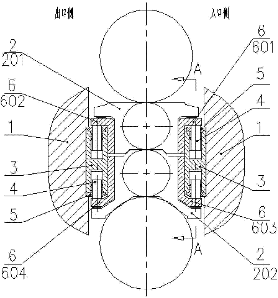
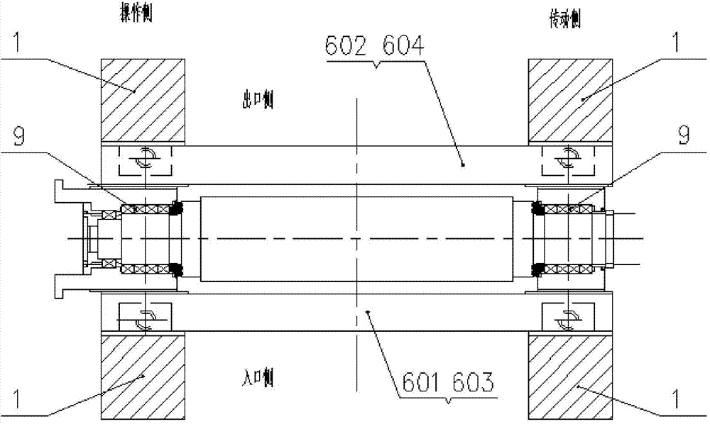
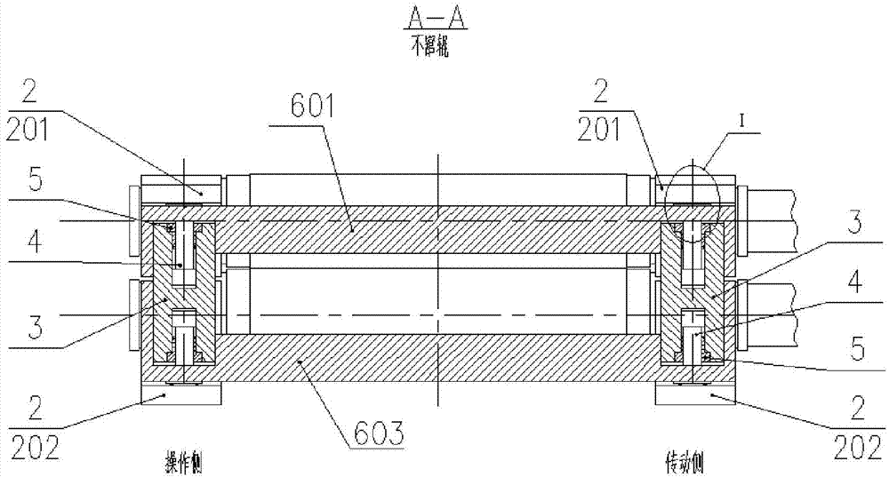
[0037] Such as figure 1 , figure 2 , image 3 , Figure 4 Shown: a work roll bending device of a four-high rolling mill, the rolling mill includes an arch 1, work rolls and backup rolls, the arch 1 is provided with a transmission side and an operation side, and the two ends of the work roll are provided with bearings seat, the work roll bearing seat 2 is set in the window of the archway, and it is characterized in that: the roll bending device includes a roll bending mechanism for providing bending force to the work roll, and the roll bending mechanism is provided with a bending block 3 And the bending beam 6, the bending block 3 is fixedly installed in the window o...


PUM


Abstract

The invention discloses a working roller bending device for a double-roller rolling machine and a roller bending force control method. The rolling machine comprises an arch, a working roller and a supporting roller. The roller bending device comprises a roller bending mechanism for supplying a roller bending force to the working roller; the roller bending mechanism is provided with roller bending blocks and a roller bending beam, wherein the roller bending block are fixedly mounted in a window of the arch and symmetrically arranged at two sides of a working roller bearing block; a piston rod and an end cover are arranged at two ends of each roller bending block; the roller bending blocks, the piston rods and the end covers form a roller bending hydraulic cylinder; the piston rods act on the roller bending beam. According to the roller bending device, a fixed single oil cylinder is adopted according to the structure, and micro differential pressure control is performed; compared with the prior art, the roller bending device has the advantages that the capacity is fully utilized, the maintenance points are few, and the quantity of the oil cylinders is decreased.

Description

technical field [0001] The invention belongs to the field of plate / strip hot rolling, and relates to a work roll bending device and a roll bending force control method of a four-high rolling mill, and is particularly suitable for rolling mills requiring axial roll shifting of work rolls. Background technique [0002] In the field of plate / strip hot rolling, the work roll bending device is an important device for shape control, and its bending force is applied to the work roll chock by a hydraulic cylinder. However, in rolling mills that require axial shifting of the work rolls, in order to ensure that the roll bending force always acts on the center of the roll bearing under the shifting state, patents CN201320204637. CN200710203401.7 discloses a differential pressure control scheme for fixed double oil cylinders. [0003] Although the above-mentioned scheme has also solved the problem of the eccentric load of the work roll bearing, it has brought new problems at the same t...

Claims


Application Information

Patent Timeline
Patent Type & Authority Applications(China)
IPC IPC(8): B21B31/32B21B28/04B21B37/40
Inventor 蒋周强黄焕江周尚文
Owner CISDI ENG CO LTD
Why Eureka
Try Eureka