Method and device for performing combined removal on boiler flue gas particulates and heavy metals

A technology for combined removal and boiler flue gas, applied in combined devices, separation methods, chemical instruments and methods, etc., can solve the problems of low removal efficiency, poor hydrophilicity, and inability to remove, and achieve high removal efficiency, Improve adsorption efficiency and efficient mercury removal

Inactive Publication Date: 2015-07-01
ELECTRIC POWER RES INST OF GUANGDONG POWER GRID +1
View PDF7 Cites 11 Cited by
  • Summary
  • Abstract
  • Description
  • Claims
  • Application Information

AI Technical Summary

Problems solved by technology

[0003] Mercury in flue gas is classified as particulate mercury Hgp and elemental mercury Hg 0 and oxidized mercury Hg 2+ Three forms exist, of which particulate mercury Hg p Can be removed by dust collector, oxidized mercury Hg 2+ It can be absorbed and removed in the wet removal system, and can also be adsorbed and converted into particulate state and captured and removed. Elemental state Hg 0 Due to the gaseous state and poor hydrophilicity, the removal efficiency of dust collector and wet removal system is low
Although the flue gas passes through the SCR system, a small amount of elemental mercury Hg 0 Will be oxidized to oxidized mercury Hg 2+ , but there is still a considerable proportion of elemental mercury Hg 0 Cannot be removed by conventional flue gas cleaning systems

Method used


Image

  • Method and device for performing combined removal on boiler flue gas particulates and heavy metals
  • Method and device for performing combined removal on boiler flue gas particulates and heavy metals

Examples


Embodiment Construction

[0015] The method and device of the present invention will be described in detail below in conjunction with the accompanying drawings.

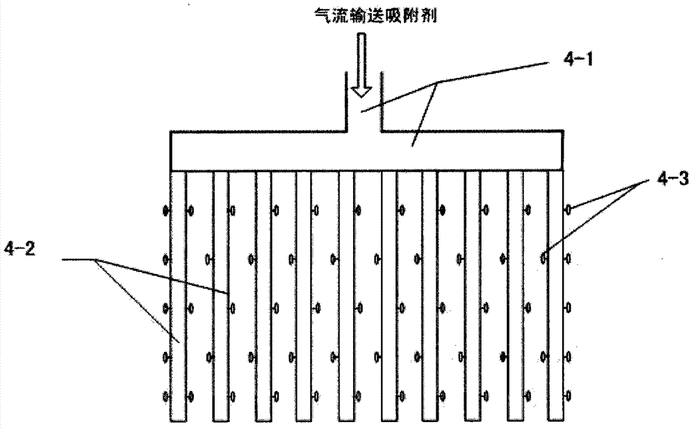
[0016] see figure 1 , a device for joint removal of boiler flue gas particles and heavy metals, along the direction of flue gas flow, in a hollow shell (1), there are successively provided with electric dust removal areas (2), fixed beds of mercury catalytic oxidizers ( 3), the adsorbent injection system (4) and the bag type dust removal area (5); the dust hopper (6) is arranged under the electrostatic precipitator area and the bag type dust removal area. A smoke inlet (7) is arranged on one side of the casing, and a smoke outlet (8) is arranged on the other side of the casing.

[0017] The high-concentration flue gas of the coal-fired boiler first passes through the electrostatic precipitator area (2) for dust removal and filtration to remove most of the particulate matter and some particulate heavy metals, and collects the fly ash particle...


PUM


Abstract

The invention discloses a method and a device for performing combined removal on boiler flue gas particulates and heavy metals. The device comprises an electrostatic precipitation area, a heavy metal catalytic oxidation area, an adsorbent injection area and a bag-type dust removal area. The method comprises the following steps: allowing boiler flue gas to pass through the electrostatic precipitation area, efficiently capturing the particulates and the particle state heavy metals such as mercury and arsenic by virtue of an electrostatic precipitator, allowing the flue gas to pass through a mercury catalytic oxidizer fixed bed, converting zero-valent mercury into divalent mercury in the flue gas, injecting activated carbon behind the catalytic oxidizer fixed bed so as to adsorb and remove the heavy metals such as mercury and arsenic, and allowing the activated carbon adsorbing the heavy metals and escaping fly ash to enter a bag area so as to be captured. Original quality coal ash is discharged by an electric area ash bucket, the activated carbon adsorbing the heavy metals and a small amount of coal ash are discharged by a bag-area ash bucket, a small amount of discharge is realized, and most of a mixture circulates to a pipeline to be injected into the flue gas to be recycled. According to the device and the method provided by the invention, the combined removal on the particulates and the heavy metals can be effectively realized, and the efficiency of removing the heavy metals in the coal-fired flue gas is greatly improved.

Description

technical field [0001] The invention belongs to the fields of energy utilization and environmental protection, and relates to a method and a device for jointly removing particulate matter and heavy metals in flue gas of coal-fired boilers. Background technique [0002] Mercury and arsenic are chemical substances with severe physiological toxicity, strong bioaccumulation, carcinogenic and teratogenicity, and are major environmental problems that threaten human health and ecological security. The massive consumption of coal around the world has made coal burning the main source of man-made pollution of arsenic and mercury. Following the dust, SO 2 After NOx and NOx, heavy metals are generally regarded as another focus of flue gas pollution control, especially mercury and arsenic have become research hotspots. With the increasingly stringent emission standards for heavy metals in coal-fired flue gas, it is imperative to use appropriate technical methods to achieve efficient r...

Claims


Application Information

Patent Timeline
Patent Type & Authority Applications(China)
IPC IPC(8): B01D53/74B01D53/64B01D50/00B01D53/10
Inventor 李德波吕建燚陆义海
Owner ELECTRIC POWER RES INST OF GUANGDONG POWER GRID
Why Eureka
Try Eureka