
A kind of air lifting mud suction device and its application

A technology of air lift and mud suction pipe, which is applied to the feeding/discharging device of the sedimentation tank, etc., can solve the problem that the normal sludge discharge of the coagulation sedimentation tank cannot be realized, the sludge at the bottom of the pool is not easy to be pumped up, and the air lift effect is poor, etc. problem, to achieve good operation effect, improve mud-water separation effect, and improve the effect of efficiency

Active Publication Date: 2017-07-28
INNER MONGOLIA SAIAOQI ENVIRONMENTAL PROTECTION TECH CO LTD
View PDF7 Cites 0 Cited by
  • Summary
  • Abstract
  • Description
  • Claims
  • Application Information

AI Technical Summary

Problems solved by technology

However, the air pipes of the air-lift dredging device are all opened from the pipe head, and the air flow is unstable, and the air-lift effect is poor.
[0007] In sewage treatment facilities, the coagulation sedimentation tank belongs to the advanced treatment part of the sewage treatment process. Compared with the sludge in the secondary sedimentation tank, the sludge in the coagulation sedimentation tank has a large amount of sludge, strong sludge viscosity, and is not easy to The sludge at the bottom of the tank is pumped up through the siphon method of the general scraper and suction machine and the liquid level difference; especially when the sludge in the sedimentation tank is relatively viscous or there is too much sludge at the bottom of the tank, the air lift device of the above patent is used The suction dredger cannot realize the normal sludge discharge of the coagulation sedimentation tank

Method used


Image

  • A kind of air lifting mud suction device and its application
  • A kind of air lifting mud suction device and its application
  • A kind of air lifting mud suction device and its application

Examples


Embodiment Construction

[0033] The present invention can be further clearly understood through the specific examples of the present invention given below, but they are not intended to limit the present invention. Parts that are not described in detail in the detailed description are obtained by using existing technologies, known technical means and industry standards.

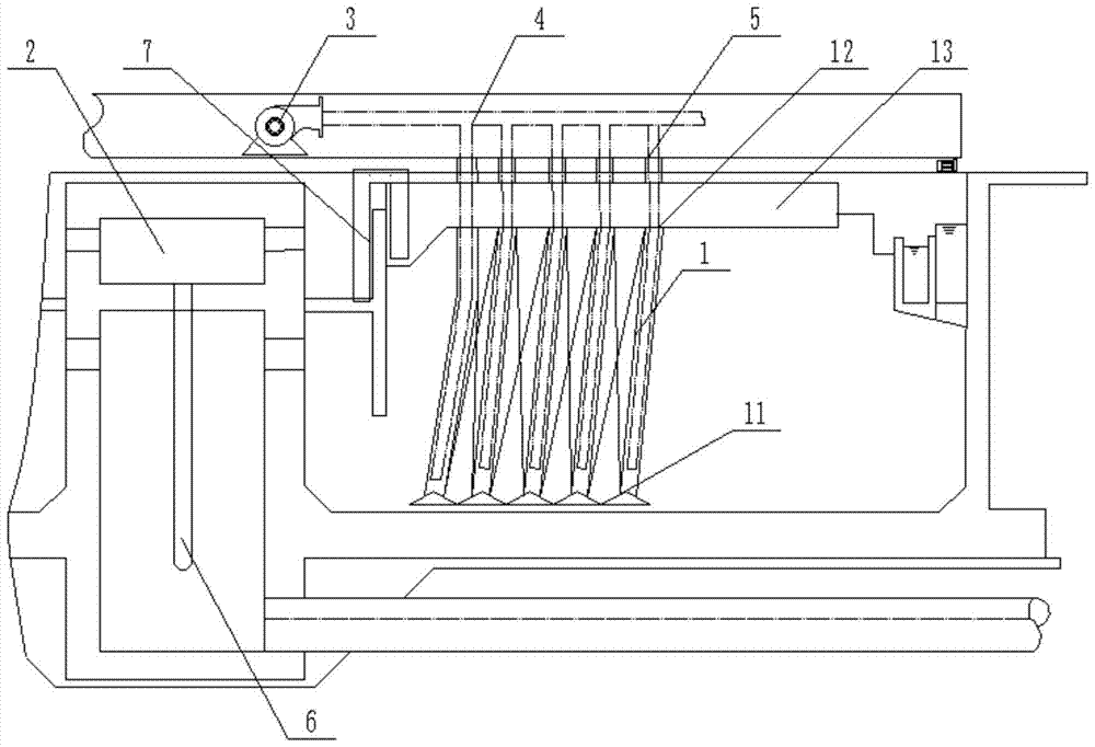
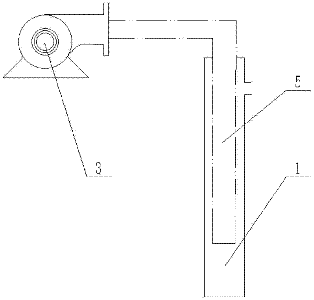
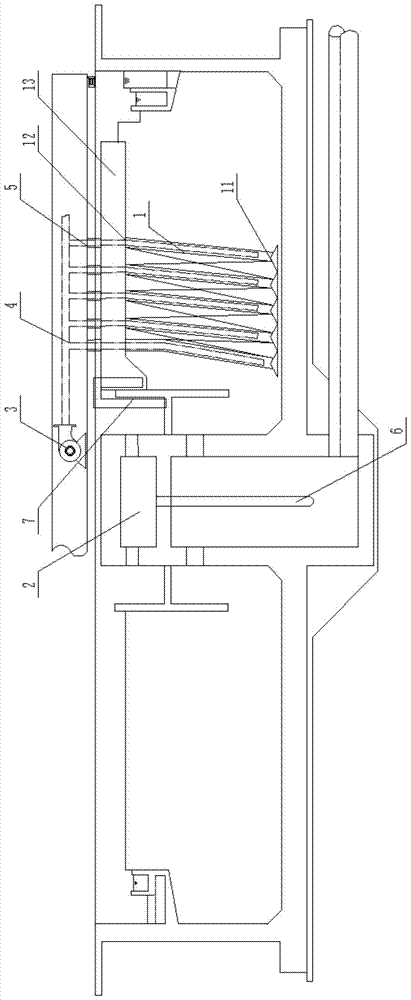
[0034] Please refer to the attached Figures 1 to 2 , the airlift mud suction device of the present invention can be applied to the coagulation sedimentation tank scraper suction mud machine, including

[0035] Five suction pipes 1,

[0036] The mud collecting tank 13 is connected with five mud suction pipes 1, and is used to concentrate the sludge transported by the mud suction pipe 1;

[0037] Mud barrel 2, used to concentrate sludge;

[0038] Blower 3;

[0039] Air pipe 4; connected with blower 3, used to deliver compressed air;

[0040] Five air pipes 5 are connected to the air pipe 4; each air pipe 5 is inserted into the cor...


PUM


Abstract

The invention discloses a gas stripping mud suction device and application thereof. The gas stripping mud suction device comprises a plurality of mud suction pipes, a mud collection groove connected with the plurality of mud suction pipes, an air blower, an air passage connected with the air blower and used for conveying compressed air, and a plurality of air pipes connected onto the air pipeline, wherein the quantity of the air pipes is the same as that of the mud suction pipes; and each air pipe is inserted into the corresponding mud suction pipe. By virtue of the structure that the air pipes are inserted into the corresponding mud suction pipes, the stability of airflow in the air pipes of the gas stripping mud suction device is guaranteed and the gas stripping effect is greatly improved; the mud discharging requirements of great amount and strong viscosity in a coagulating precipitation tank of sewage treatment can be met; the gas stripping mud suction device has a good operation effect and the mud-water separation effect can be improved so that the water quality reaches the standard to be discharged; and compared with a traditional mud scraping and suction machine, the efficiency is greatly improved and the gas stripping mud suction device can be applied to the mud scraping and suction machine of the coagulating precipitation tank.

Description

technical field [0001] The invention relates to the technical field of dredges, and particularly discloses an air-lift dredging device and its application. Background technique [0002] The scraper and suction machine is mainly used in circular sedimentation tanks with large diameters in urban sewage treatment plants, waterworks and industrial wastewater treatment, to remove the sludge settled at the bottom of the tank and to skim the scum on the surface of the tank. The mud scraper and suction machine is composed of a driving device, a working bridge, a main mud scraping device, an auxiliary mud scraping device, a central turntable, a scum skimming device, an overflow weir plate and a slag retaining plate, and a current collecting device. For the sedimentation tank with water outlet around the center water inlet, it is generally necessary to set up a guide tube. Its working principle is: the driving device drives the scraper and suction machine to rotate around the center ...

Claims


Application Information

Patent Timeline
Patent Type & Authority Patents(China)
IPC IPC(8): B01D21/24
Inventor 巴雅尔
Owner INNER MONGOLIA SAIAOQI ENVIRONMENTAL PROTECTION TECH CO LTD
Learn More