Plant-cultivating method after laser-beam divergence
A technology for cultivating plants and laser beams is applied in the field of cultivating plants after the divergence of laser beams, which can solve the problems of high energy consumption of artificial light sources, and achieve the effects of reducing energy consumption and high utilization rate of light energy.
- Summary
- Abstract
- Description
- Claims
- Application Information
AI Technical Summary
Problems solved by technology
Method used
Image
Examples
Embodiment 1
[0048] Embodiment 1 is used for the laser beam diverging device of A and the plant cultivation method using the device
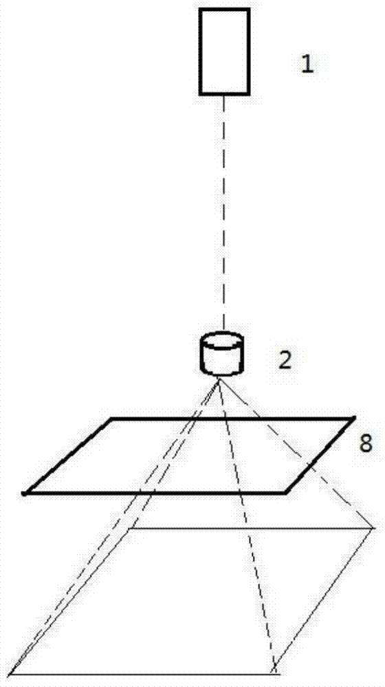
[0049] A laser beam diverging device for A, the structure of which is as figure 1 As shown, it is composed of a laser emitter 1, a pattern lamp holder 2 located below it, and a uniform light plate 8.
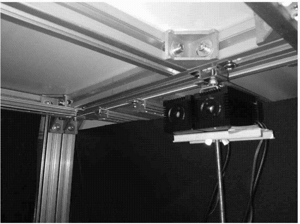
[0050] Laser emitter 1 can be provided with several sets according to the kind of laser used (N kinds of laser just use N sets). The laser emitter 1 used in this embodiment is two, a red light (660nm) laser emitter and a blue light (460nm) laser emitter, its photo is shown in figure 2 , where the left side of the photo is a blue laser transmitter with a specification of 500MW, and the right side of the photo is a red laser transmitter with a specification of 500MW. The blue laser beam and the red laser beam respectively emitted by the two laser emitters converge at the gobo lamp head.
[0051] The pattern lamp head used in this embodiment is a commercially...
Embodiment 2
[0055] Embodiment 2 is used for the laser beam diverging device of B1 and the plant cultivation method using the device
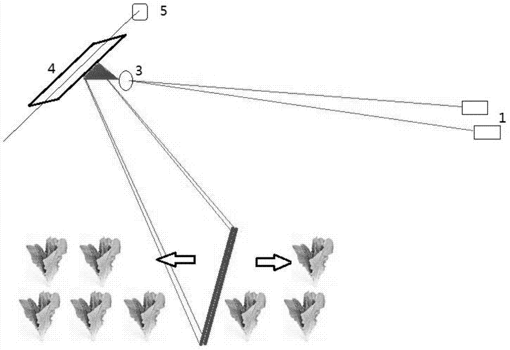
[0056] For the laser beam diverging device used in B1, its structure diagram is shown in image 3 , consisting of a laser transmitter 1, a straight lens 3, a mirror 4 and a motor 5 that drives the mirror to reciprocate and swing; the laser beam emitted by the laser transmitter 1 is converted into a linear light band by the straight lens 3, and then projected onto the On the reciprocating mirror 4, after reflection, a reciprocating scanning light band is formed below.
[0057] The photo of the used reflector 4 and the motor 5 that drives the reflector to swing back and forth in this embodiment is shown in Figure 4 .
[0058] The present embodiment has used 3 kinds of laser beam source configurations (3 kinds of laser emitter configurations):
[0059] a red laser beam (a red laser transmitter)
[0060] b Combination of red laser beam and blue laser beam ...
Embodiment 3
[0067] Embodiment 3 is used for the laser beam diverging device of B2 and the plant cultivation method using the device
[0068] For the laser beam diverging device used in B2, its structure diagram is shown in Figure 7 , consists of a laser transmitter 1, a straight-line lens 3, a polygonal mirror 6 and a motor 5 that drives the rotation of the polygonal mirror; the laser beam emitted by the laser transmitter 1 is converted into a linear light strip by the straight-line lens 3, and then projected onto the rotating polygonal mirror 6, after reflection, a repeated scanning light band is formed below.
[0069] The polygonal mirror used in this embodiment is a hexagonal mirror, which can be replaced with other polygonal mirrors that can achieve the same scanning effect.
[0070] Carry out 3 kinds of laser beam light source configurations with reference to embodiment 2, detect the light band that produces and set the cultivation plate position, its requirement also refers to emb...
PUM
| Property | Measurement | Unit |
|---|---|---|
| Wavelength | aaaaa | aaaaa |
| Wavelength | aaaaa | aaaaa |
Abstract
Description
Claims
Application Information
 - R&D Engineer
- R&D Manager
- IP Professional
- Industry Leading Data Capabilities
- Powerful AI technology
- Patent DNA Extraction
Browse by: Latest US Patents, China's latest patents, Technical Efficacy Thesaurus, Application Domain, Technology Topic, Popular Technical Reports.
© 2024 PatSnap. All rights reserved.Legal|Privacy policy|Modern Slavery Act Transparency Statement|Sitemap|About US| Contact US: help@patsnap.com


