
Method for in-line calibration of an industrial robot, calibration system for performing such a method and industrial robot comprising such a calibration system

A technology of industrial robots, calibration methods, applied in general control systems, control/regulation systems, instruments, etc.

Inactive Publication Date: 2015-06-24
INOS AUTOMATIONSSOFTWARE
View PDF10 Cites 29 Cited by
  • Summary
  • Abstract
  • Description
  • Claims
  • Application Information

AI Technical Summary

Problems solved by technology

While it is not necessary to estimate the full orientation of the end effector to perform the calibration, a measurement system that extracts the 6D orientation (position and orientation) of the end effector enables the calibration method to use a smaller number of calibration orientations (since more constraints are applied to each measuring)

Method used


Image

  • Method for in-line calibration of an industrial robot, calibration system for performing such a method and industrial robot comprising such a calibration system
  • Method for in-line calibration of an industrial robot, calibration system for performing such a method and industrial robot comprising such a calibration system
  • Method for in-line calibration of an industrial robot, calibration system for performing such a method and industrial robot comprising such a calibration system

Examples


Embodiment Construction

[0057] In the following, the calibration system according to the invention is effectively described in detail. Calibration provides online compensation for inaccuracies in robotic applications. Furthermore, the system is portable, highly accurate, time-sensitive and cost-effective. In the following, methods and systems are described using the example of thermal compensation. Of course, the invention is not limited to the described example of thermal compensation. There are many sources of error that lead to inaccuracies in robot position, including manufacturing tolerances during production of the robot, thermal effects, encoder offset, compliance of the arms, gear transmission errors, and backlash in the gear transmission. All of these can be compensated for by the calibration method and system according to the invention.

[0058] Furthermore, the invention is not limited to a particular kind of two-dimensional optical position sensor, but any kind of suitable sensor, inde...


PUM


Abstract

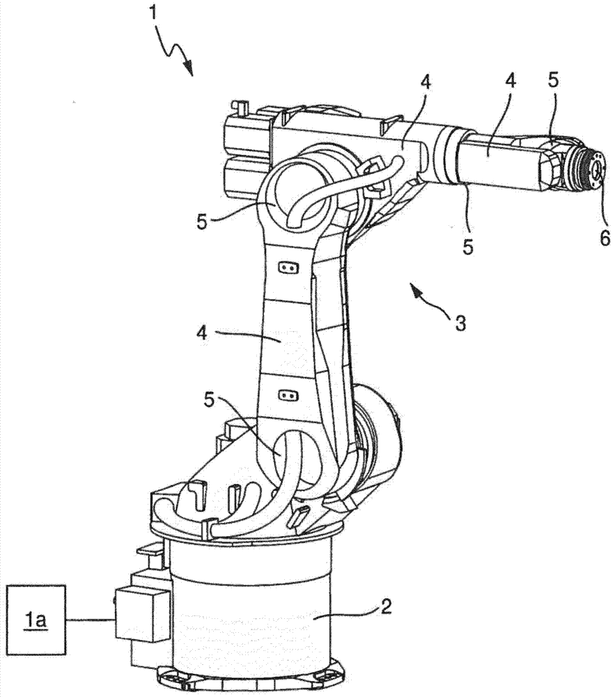
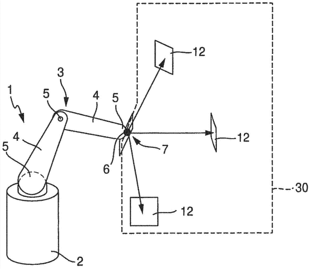
The invention refers to a method for in-line calibration of an industrial robot (1). The robot (1) comprises a fixed base section (2) and a multi chain link robot arm (3). The chain links (4) are interconnected and connected to the base section (2) of the robot (1), respectively, by means of articulated joints (5). An end effector (6) of the robot arm (3) can be moved in respect to the base section (2) within a three-dimensional workspace into any desired location. The idea is to move the end effector (6) into a predefined calibration location and to determine characteristic parameters of the robot (1) for that location. The characteristic parameters are compared to previously acquired values of the corresponding parameters for that calibration location. The differences between the characteristic parameters of the current location and the previously acquired parameters are used for correcting the kinematic model of the robot (1) and during normal operation of the robot (1) to enhance the accuracy of movement of the distal end (6). The end effector (6) is moved exactly into the calibration location by means of an iterative closed loop control process, in which light sources (7) fixedly connected to the end effector (6) emit light rays which impact on at least one optical position sensor (12) fixedly positioned in respect to the robot base (2). The end effector (6) is moved such that the actual ray positions (20) on the sensors (12) are moved to a predefined position (20') corresponding to the predefined calibration location by means of the iterative process.

Description

technical field [0001] The present invention relates to a method for on-line calibration of industrial robots, to a calibration system for on-line calibration of industrial robots and to industrial robots. The robot consists of a fixed base section and a multi-link robot arm. Via articulated joints, the chain links are respectively connected to each other and to the base part of the robot. The distal end of the robotic arm can be moved in three dimensions relative to the base portion to a desired position and orientation hereinafter referred to as orientation. Background technique [0002] In general, robot calibration is the process of using software to enhance the positional accuracy of a robot. Its purpose is to identify the exact kinematic properties of the robot, which will establish a mapping between joint angles and positions of end effectors at the distal end of the robot arm in Cartesian space. There can be many sources of error that lead to inaccuracies in the r...

Claims


Application Information

Patent Timeline
IPC IPC(8): B25J9/16
CPCB25J9/1612B25J9/1628B25J9/1692G05B2219/39018G05B2219/39043G05B2219/39046G05B2219/39048G05B2219/39056G05B2219/39391G05B2219/39394G05B2219/39397
Inventor 马太·阿里弗朗基斯亚历山德罗斯·布甘斯安德里亚斯·戴蒙普罗斯哈拉兰博斯·塔萨科斯
Owner INOS AUTOMATIONSSOFTWARE
Learn More