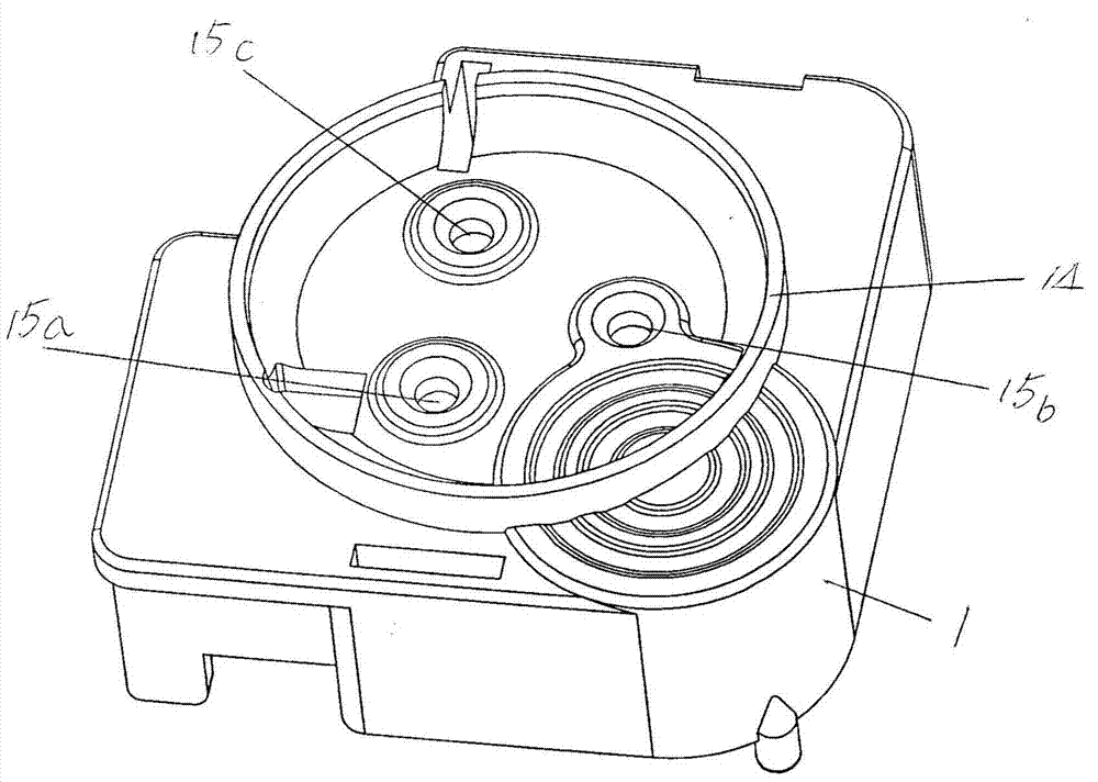
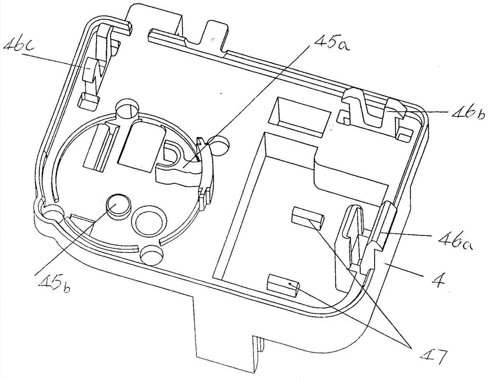
[0005] But the single-phase AC motor starter of aforementioned CN100581043C still has the following shortcoming: First, although both sides of the bottom of the positive
temperature coefficient thermistor are contacted with the top protrusion, the gap between the positive
temperature coefficient thermistor and the shell can be significantly reduced. The supporting area in the cavity of the positive temperature coefficient thermistor can significantly reduce the volume of the positive temperature coefficient thermistor, for example, the weight is reduced from 35-40g to 15-16g, but due to the small size of the positive temperature coefficient thermistor The side edges in the circumferential direction (the applicant defines them as the front and rear side edges) still need to be in contact with the front and rear walls of the positive temperature coefficient thermistor cavity in a large area, so it is not enough to reflect the ultimate energy-saving effect. The volume of the coefficient thermistor is still too large, and the weight is still too heavy
Theoretically speaking, forming a support wall on the front and rear cavity walls of the positive temperature coefficient thermistor cavity and forming a protrusion on the support wall can make up for the aforementioned deficiency and further reduce the volume of the positive temperature coefficient thermistor. The weight can be further reduced and the energy-saving effect can be reflected to the extreme degree, but repeated experiments by the applicant show that this idea is not advisable, because on the one hand, the aforementioned first and second pins and the positive temperature coefficient thermistor On the other hand, due to the excessive occupation of the space in the width direction of the positive temperature coefficient thermistor cavity, the installation of the starter is troublesome; secondly, because it is formed in the positive temperature coefficient thermistor cavity The structure of a pair of supporting walls at both ends of the device is relatively complicated, which leads to a relatively complicated mold for manufacturing the shell; third, since the top protrusion is formed on the
supporting wall, the bottom of the positive temperature coefficient thermistor, that is, the bottom surface, is in contact with the The distance between the cavity bottom of the positive temperature coefficient thermistor cavity is the sum of the height of the support wall and the height of the top protrusion, so the situation of excessively raising the positive temperature coefficient thermistor causes the positive temperature coefficient thermal The positive temperature coefficient thermistor cavity protrudes from the upper part of the sensitive
resistor, and the protruding part needs to be compensated by the raised cavity on the cover (the protruding part penetrates into the raised cavity), which increases the complexity of the cover on the one hand On the other hand, the contact area between the positive temperature coefficient thermistor and the raised cavity is increased, and on the other hand, in order to ensure that the first and second pins are in the center position corresponding to the two sides of the positive temperature coefficient thermistor, the The positive temperature coefficient thermistor is reliably held and the position of the first and second pins must be moved upwards so that the
support point between the first and second pins and the
cavity wall of the positive temperature coefficient thermistor cavity (with the
support point of the
cavity wall) The contact part) moves to the upper cavity of the positive temperature coefficient thermistor cavity, which will affect the installation stability of the entire starter. For example, the first and second pins are separated from the positive temperature coefficient thermistor cavity. Concerns, which in turn lead to failure of electrical contact between the first and second pins and the positive temperature coefficient thermistor
Of course, by increasing the size of the housing in the height direction and thereby deepening the depth of the PTC thermistor cavity, the PTC thermistor can be located in the PTC thermistor cavity as a whole and can make up for the aforementioned disadvantages. Factors, but such a design will significantly increase the volume of the housing, that is, the problem of losing
sight of the other; Fourth, because the first pin is in contact with the first pin reed on one side of the positive temperature coefficient thermistor (the patent claims No. One spring piece) and the second pin reed (the patent is called the second spring piece) in which the second pin is in contact with the surface of the other side of the positive temperature coefficient thermistor are in a straight line with the positive temperature coefficient thermistor The surface of the positive temperature coefficient thermistor is in contact, that is, the first and second pin reeds are both horizontally parallel to each other and fully correspond to each other, so when the
electric spark is generated, the positive temperature coefficient thermistor will produce many cracks, because the opposite sides are still covered. The corresponding first and second pin reeds are elastically supported, and the cracked (cracked) part of the elastically supported positive temperature coefficient thermistor continues to be clamped in the original position stably, while the remaining fragments are scattered , so the power continues to pass through the elastically supported remnants of the PTC thermistor, causing these remnants and their associated first and second prong reeds to melt into each other, followed by a certain The result is an electrical
short circuit between the first and second pins, which in turn further accelerates the generation of abnormal heat, which is very likely to force further failures of the device, such as causing shell failure. Body
softening deformation, etc.
[0006] As far as the above-mentioned shell cover of CN100581043C is concerned, there are the following deficiencies: First, it is necessary to form six baffles for blocking the pins (including grounding pins, N pins and L pins) on the shell cover and towards the side of the housing , four anti-movement limit stops to prevent pins from moving and five supporting flanges for supporting pins (for details, please refer to
paragraph 2 on page 5 to
paragraph 1 on page 6 of the patent specification), Therefore, it not only significantly increases the complexity of the cover structure, but also affects the installation efficiency of the pins; secondly, because the structure of the cover itself is unreasonable, the pins (that is, the grounding pins) must be connected before the cover is attached to the housing. , N pins and L pins) for
assembly, that is to say, first insert the pins into the corresponding pin slots (that is, pin holes) preset on the cover, and then fit the cover together with the pins with the shell, and then assemble Efficiency will be seriously affected, because pre-installing the pins on the cover will interfere with the cover when
mating with the shell, and the stability of the pins is also difficult to guarantee, and there is a risk of deflection and loosening
[0007] As far as the above-mentioned single-phase AC motor protector of CN100581043C is concerned, there are the following deficiencies: since the fixed seat only has a pin chamber for the spring piece and the pin (the patent is called the first pin) to accommodate it, when the spring piece and the pin are accommodated in After the pin cavity, the positioning effect of the fixing seat on the spring piece and the pin is fragile, so once there is a loose displacement, it will affect the electrical contact or disconnection between the moving contact on the spring piece and the static contact on the pin Effect


