Thrower

A throwing machine and frame technology, which is applied in the field of throwing machines, can solve problems such as the deviation of the throwing belt and the unstable operation of the throwing machine, and achieve the effect of stable operation and accurate throwing

Active Publication Date: 2015-06-24
CHINA ENFI ENGINEERING CORPORATION
View PDF6 Cites 0 Cited by
  • Summary
  • Abstract
  • Description
  • Claims
  • Application Information

AI Technical Summary

Problems solved by technology

However, when the speed of the throwing belt is high, it will directly cause the throwing belt to deviate, resulting in unstable operation of the throwing machine

Method used


Image

  • Thrower
  • Thrower

Examples


Embodiment Construction

[0023] Embodiments of the present invention are described in detail below, examples of which are shown in the drawings, wherein the same or similar reference numerals designate the same or similar elements or elements having the same or similar functions throughout. The embodiments described below by referring to the figures are exemplary and are intended to explain the present invention and should not be construed as limiting the present invention.

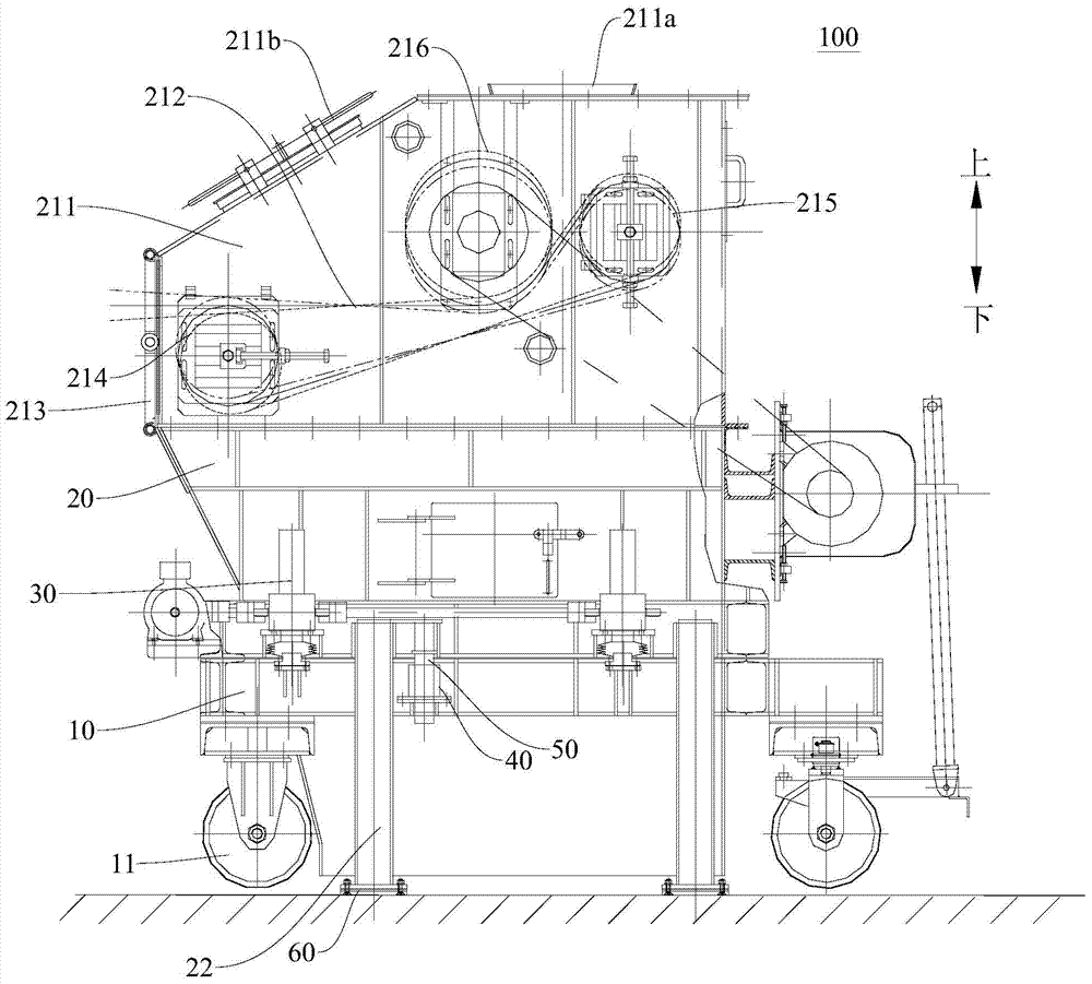
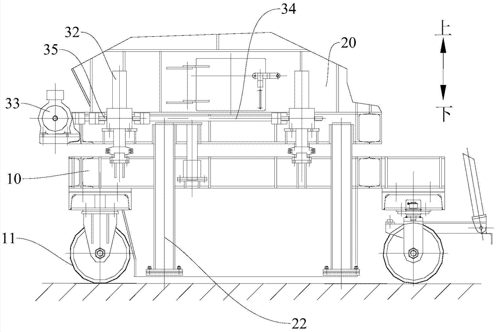
[0024] Refer below Figure 1-2 The throwing machine 100 of the embodiment of the present invention will be described.

[0025] like figure 1 As shown, the throwing machine 100 according to the embodiment of the present invention includes: a base 10 , a frame 20 and a lifting device 30 . The base 10 is provided with wheels 11, and the frame 20 is provided with a material throwing assembly and supporting legs 22. The elevating device 30 is arranged on the base 10, and the elevating device 30 is connected with the frame 20 so that...


PUM


Abstract

The invention discloses a thrower. The thrower comprises a base with wheels, a machine frame with a throwing assembly and supporting legs, and a lifting device arranged on the base, wherein the lifting device is connected with the machine frame so that the machine frame can be lifted up and put down between the rising position where the wheels are supported by the ground and the supporting legs are away from the ground and the falling position where the wheels are away from the ground and the supporting legs are supported by the ground. The thrower is stable and reliable in running and accurate in throwing.

Description

technical field [0001] The invention relates to the technical field of smelting, in particular to a throwing machine. Background technique [0002] In related technologies, during metal smelting, materials are thrown into a roasting furnace by a throwing machine. The existing throwing machine is supported by wheels, and the wheels can move the throwing machine between the working position and the maintenance position. When the throwing machine is working, the speed of the throwing belt is usually set higher, so that the materials can be projected farther and scattered more, so that the materials can be burned more fully in the roaster. However, when the speed of the throwing belt is high, it will directly cause the throwing belt to deviate, resulting in unstable operation of the throwing machine. Contents of the invention [0003] The present invention aims to solve one of the technical problems in the related art at least to a certain extent. For this reason, an object...

Claims


Application Information

Patent Timeline
Patent Type & Authority Applications(China)
IPC IPC(8): F27D3/00
Inventor 邱杰敏刘占彬李洁郝朋越贾源
Owner CHINA ENFI ENGINEERING CORPORATION
Why Eureka
Try Eureka