Self-adaptive broaching machine feeding plate

A feeding plate, self-adaptive technology, applied in the direction of gear teeth, gear cutting machines, belts/chains/gears, etc., can solve the problems of inability to guarantee relative position consistency, low qualification rate, poor product structure uniformity, etc., to achieve product structure uniformity. Good performance, high pass rate, and the effect of improving consistency

Active Publication Date: 2015-06-24
重庆成俊工贸有限公司
View PDF9 Cites 0 Cited by
  • Summary
  • Abstract
  • Description
  • Claims
  • Application Information

AI Technical Summary

Problems solved by technology

[0002] The tooth drawing process includes two processes of initial drawing and finishing drawing. The initial drawing refers to broaching the gear sleeve blank with no teeth in the inner hole, and the finishing drawing refers to correcting the gear sleeve with teeth in the inner hole to meet the product technical requirements. The feeding plate is a tool used to install the workpiece on the broaching machine table. When the traditional feeding plate is loaded into the workpiece, the workpiece can move freely in any direction for 0-3mm, that is, the circumferential direction and radial direction are not positioned, so The workpiece can move and rotate freely within a certain range. When the gear sleeve is fine-drawn, since the feeding plate has no positioning function for the gear sleeve, it is impossible to guarantee the consistency of the relative position of the workpiece on the workbench during each processing, resulting in processing The product structure uniformity is poor, and the qualified rate is low

Method used


Image

  • Self-adaptive broaching machine feeding plate

Examples


Embodiment Construction

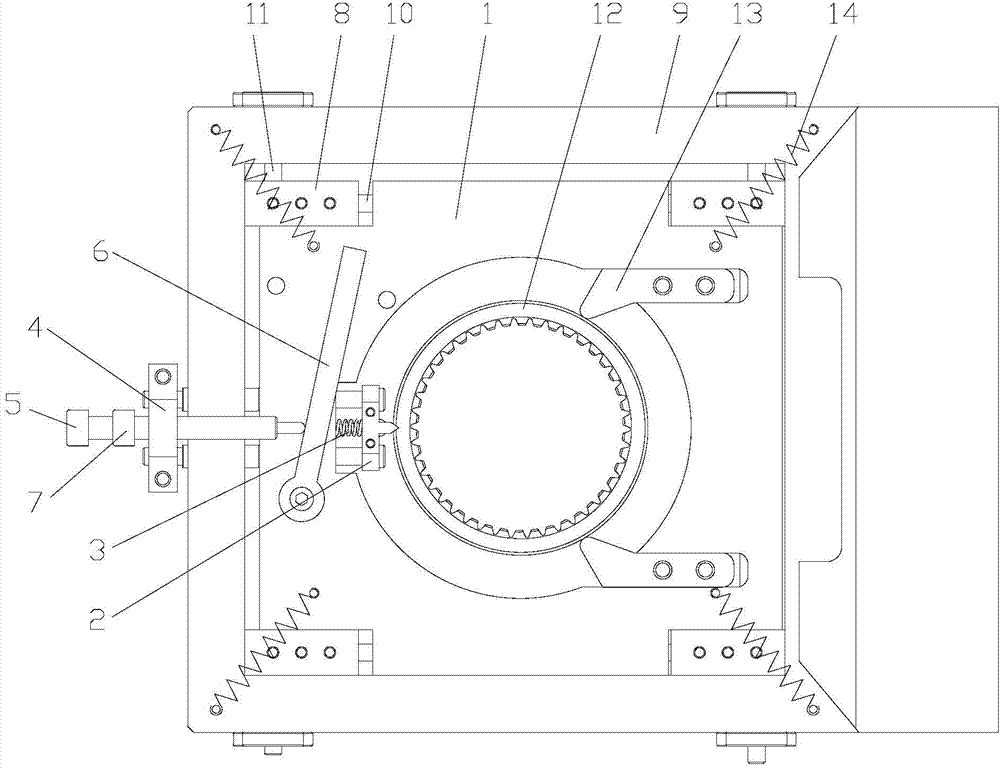
[0010] figure 1 It is a structural schematic diagram of the present invention, as shown in the figure: the self-adaptive broaching bed feeding plate of this embodiment includes a base 9, a transition piece 8, a first positioning rod 10, a second positioning rod 11, a slide plate 1 and a clamping positioning mechanism The slide plate 1 is slidably connected to the transition piece 8 through the first positioning rod 10 along the lengthwise direction of the first positioning rod 10, and the transition piece 8 is free along the length of the second positioning rod 11 through the second positioning rod 11. The first positioning rod 10 and the second positioning rod 11 are perpendicular to each other; the slide plate 1 is provided with a vertically penetrating cavity for accommodating the workpiece 12; the clamping positioning mechanism is installed on the slide plate 1 is used to clamp and position the workpiece 12 along the radial direction of the cavity; the clamping and positio...


PUM


Abstract

The invention discloses a self-adaptive broaching machine feeding plate which comprises a base, a transition part, a first positioning rod, a second positioning rod, a sliding plate and a clamping and positioning mechanism. The sliding plate is in sliding connection with the transition part in the length direction of the first positioning rod at the single degree of freedom through the first positioning rod. The transition part is in sliding connection with the base in the length direction of the second positioning rod at the single degree of freedom through the second positioning rod. The first positioning rod is perpendicular to the second positioning rod. A vertical through containing cavity for containing workpieces is formed in the sliding plate. The clamping and positioning mechanism is installed on the sliding plate and used for clamping and positioning the workpieces in the radial direction of the containing cavity. The workpieces can be clamped and positioned in the containing cavity of the sliding plate through the clamping and positioning mechanism, and are positioned in a unified mode in the circumferential direction of the workpieces. Rotation of the workpieces is limited on the condition that the workpieces are allowed to transversely move. The consistency of the relative positions of the workpieces on a workbench is improved, and the machined products are good in structure uniformity and high in percent of pass.

Description

technical field [0001] The invention relates to a tooling, in particular to an adaptive broaching machine feeding plate. Background technique [0002] The tooth drawing process includes two processes of initial drawing and finishing drawing. The initial drawing refers to broaching the gear sleeve blank with no teeth in the inner hole, and the finishing drawing refers to correcting the gear sleeve with teeth in the inner hole to meet the product technical requirements. The feeding plate is a tool used to install the workpiece on the broaching machine table. When the traditional feeding plate is loaded into the workpiece, the workpiece can move freely in any direction for 0-3mm, that is, the circumferential direction and radial direction are not positioned, so The workpiece can move and rotate freely within a certain range. When the gear sleeve is fine-drawn, since the feeding plate has no positioning function for the gear sleeve, it is impossible to guarantee the consistency ...

Claims


Application Information

Patent Timeline
Patent Type & Authority Applications(China)
IPC IPC(8): B23F23/04B23F23/06
Inventor 胡军高福臣颜学惠王兴胡成俊舒义蓉颜欢幸定军蔡屏萍
Owner 重庆成俊工贸有限公司
Why Eureka
Try Eureka