High-speed guiding and chip removing combined drill bush

A technology of guiding drill sleeves and combined drills, which is applied in the field of mechanical processing and manufacturing, can solve problems such as increased production costs, twist drill breakage, and enlarged inner holes of drill sleeves, and achieves the effect of reducing frictional resistance

Inactive Publication Date: 2015-06-24
WENZHOU POLYTECHNIC
View PDF10 Cites 4 Cited by
  • Summary
  • Abstract
  • Description
  • Claims
  • Application Information

AI Technical Summary

Problems solved by technology

However, many deficiencies have been found in the use of traditional drill sleeves: First, when drilling profiles such as aluminum, aluminum scraps will wrap around the twist drill and gradually accumulate, becoming tighter and tighter, affecting the processing quality and easily causing twist drills The drill is broken; secondly, the traditional drill sleeves are fixed, and the high-speed friction between the high-speed rotating twist drill and the drill sleeve makes the outer diameter of the twist drill smaller and reduces the shape accuracy of the twist drill. At the same time, the drill The inner hole of the sleeve becomes larger, which reduces the precision of the drill sleeve; finally, the traditional drill sleeve has become the main factor restricting the development of automatic drilling machine tools, and personnel must be arranged next to each automatic drilling machine tool to clean up aluminum chips. , and frequent replacement of drill sleeves interrupts the continuity of production, reduces production efficiency and increases production costs

Method used


Image

  • High-speed guiding and chip removing combined drill bush
  • High-speed guiding and chip removing combined drill bush

Examples


Embodiment Construction

[0019] The present invention will be further described in detail below in conjunction with the accompanying drawings, but does not constitute any limitation to the present invention. Similar component numbers in the accompanying drawings represent similar components. As mentioned above, the present invention provides a high-speed guiding and chip removal combined drill bush, which has a simple structure and is easier to operate.

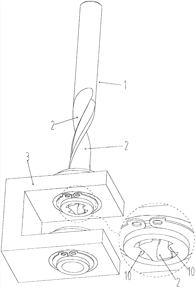
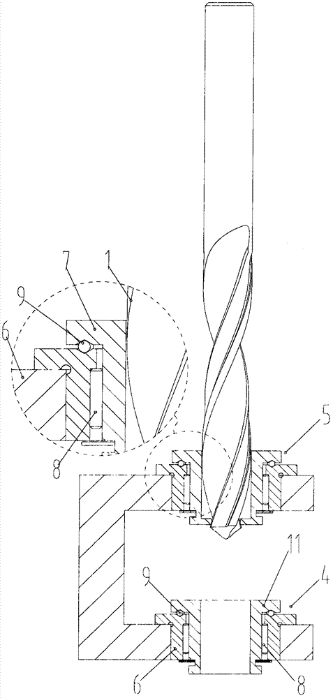
[0020] figure 1 , 2 It is a structural schematic diagram of the high-speed guiding and chip removal combined drill sleeve of the present invention.

[0021] A high-speed guide and chip removal combined drill sleeve, comprising: a guide drill sleeve 4 and a chip removal drill sleeve 5; the guide drill sleeve and the chip removal drill sleeve are coaxially arranged and fixed on a bracket It is located at the lower part of the chip removal drill sleeve, and a twist drill 1 is arranged on the upper part of the chip removal drill sleeve.

[0022] The g...


PUM


Abstract

The invention relates to the technical field of mechanical machining and manufacturing, in particular to an auxiliary tool for improving the workpiece drilling machining quality. A high-speed guiding and chip removing combined drill bush is characterized in that a guiding drill bush body and a chip removing drill bush body are included; the guiding drill bush body and the chip removing drill bush body are coaxially arranged and fixedly connected to a support, the guiding drill bush body is located on the lower portion of the chip removing drill bush body, the guiding drill bush body and the chip removing drill bush body has an interval of twenty millimeters to thirty millimeters, and a twist drill is arranged on the upper portion of the chip removing drill bush body. The high-speed guiding and chip removing combined drill bush is used for positioning and guiding a tool to perform drilling machining, aluminum chips are prevented from winding on the twist drill, the straightness of the central axis of the twist drill is remained, the shape precision of the twist drill and the drill bush is remained, the machining precision is improved, and the production continuity is remained.

Description

technical field [0001] The invention relates to the technical field of machining and manufacturing, in particular to an auxiliary tool for improving the drilling quality of workpieces. Background technique [0002] Machine tool fixture is a kind of process equipment designed for a certain process of a workpiece produced in medium batches and above. It has a direct impact on the quality of parts processing, production efficiency and product cost. Therefore, no matter in traditional manufacturing In modern manufacturing systems, machine tool fixtures are important process equipment. [0003] Drilling jigs are fixtures used on drilling machines to ensure the accuracy of drilling and the dimensional accuracy and position accuracy of the hole spacing between holes to meet the needs of mass production. [0004] Refer to Chinese patents, patent numbers: 201410557311.8, 201420610149.7, 201420605263.0, which all involve the application of drill sleeves in product processing. Drill ...

Claims


Application Information

Patent Timeline
IPC IPC(8): B23B49/02B23Q11/00
CPCB23B49/02B23Q11/0042
Inventor 余胜东
Owner WENZHOU POLYTECHNIC
Why Eureka
Try Eureka