
Vehicle-mounted battery cooling device

A technology of vehicle battery and heat dissipation device, which is applied in the direction of secondary battery, battery pack components, and secondary battery repair/maintenance, etc. Test analysis, good mechanical protection performance, easy processing effect

Inactive Publication Date: 2015-06-17
苏州峰通光电有限公司
View PDF9 Cites 7 Cited by
  • Summary
  • Abstract
  • Description
  • Claims
  • Application Information

AI Technical Summary

Problems solved by technology

[0005] For this reason, the technical problem to be solved by the present invention is that the structure of the cooling device in the prior art is fragile and unstable, and the heat dissipation of the battery box is not uniform, thereby proposing a vehicle-mounted battery cooling device

Method used


Image

  • Vehicle-mounted battery cooling device
  • Vehicle-mounted battery cooling device
  • Vehicle-mounted battery cooling device

Examples


Embodiment 1

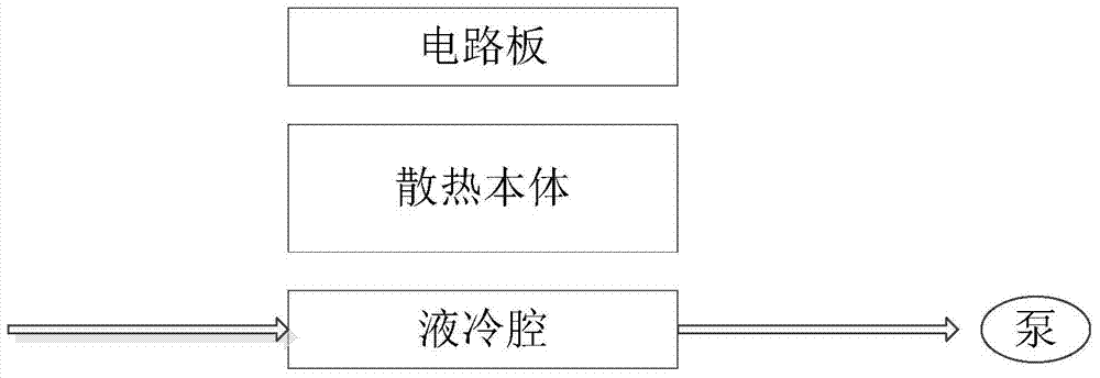
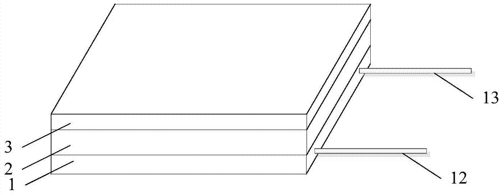
[0036] This embodiment provides a vehicle-mounted battery cooling device, such as figure 1 and 2 As shown, it includes a liquid cooling chamber 1 and a heat dissipation body 2 disposed on one surface of the liquid cooling chamber 1 . Wherein the heat dissipation body 2 can be an aluminum body, the aluminum body has a higher thermal conductivity and therefore has a good heat dissipation effect, but has poor strength. The heat dissipation body 2 can also be an aluminum alloy body or a metal body, and the actual requirements of heat dissipation performance, strength, weight and cost should be comprehensively considered in specific cases.

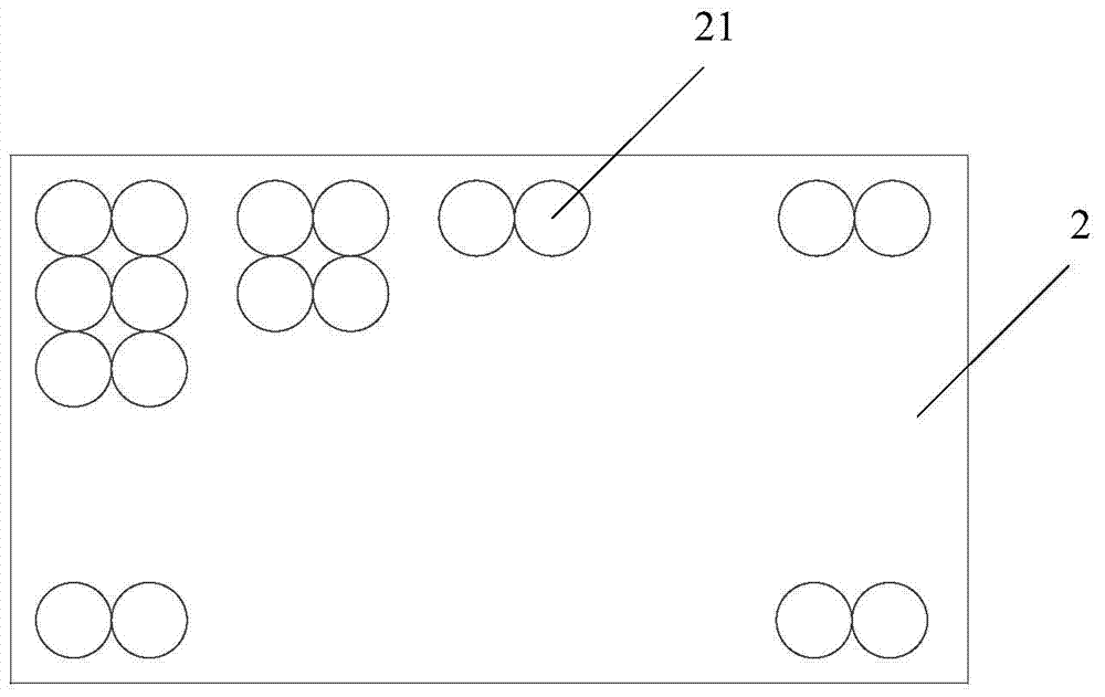
[0037] One surface of the heat dissipation body 2 is formed with several battery slots 21, each of the battery slots 21 is suitable for placing two vehicle batteries 22, the depth of the battery slots 21 is greater than the height of the vehicle batteries 22, and the Conductors in contact with the positive and negative poles of the on-vehicle...

Embodiment 2

[0047] On the basis of Embodiment 1, this embodiment also includes a circuit board 3, which is provided with a contact point conducting with the positive pole and the negative pole of the vehicle battery 22, and the circuit board 3 is covered on the surface of the battery slot 21 and The on-board battery 22 is electrically connected. In addition, the circuit board 3 can also be provided with an acquisition chip as required to collect the current and voltage of each on-board battery 22, and the circuit board 3 is provided with a battery charging circuit that can be used for the on-board battery. The battery 22 is charged, and the arrangement of the battery pack and the design of the circuit board can facilitate testing and analysis of the battery cells and rapid replacement. Since the circuit board 3 is covered on the heat dissipation body, the circuit board, heat dissipation The main body and the liquid cooling chamber form a three-layer structure, which has good mechanical pro...


PUM

PropertyMeasurementUnit
Diameteraaaaaaaaaa

Abstract

The invention provides a vehicle-mounted battery cooling device including a liquid cooling chamber and a heat radiating body arranged on one surface of the liquid cooling chamber, a plurality of battery grooves are formed on one surface of the heat radiating body, and each of the battery grooves is suitable for placing two a vehicle-mounted batteries. The cooling device adopts the cooling device heat radiating body as a structural element, the structural strength is strengthened, the inner part can be cooled, and the external part can be strengthened. The batteries can be fixed by the battery grooves, battery shift phenomenon in the vehicle movement process can be prevented, safety is high; the battery groove depth is greater than battery height, and heat dissipation area increase can be facilitated, so that the battery heat dissipation is even. The cooling fluid flow in the liquid cooling chamber of the cooling device can drive an overall decrease in temperature.

Description

technical field [0001] The invention relates to the field of electric vehicle manufacturing, in particular to a heat dissipation device for a vehicle-mounted battery of the electric vehicle. Background technique [0002] With the global energy shortage and the continuous improvement of people's awareness of environmental protection, the electric vehicle industry has developed rapidly in recent years. As the core component of electric vehicles, the performance of batteries directly affects the performance of electric vehicles. During the operation of electric vehicles, the battery will generate a lot of heat. If the heat cannot be discharged in time, the temperature of each component of the battery will rise, exceeding the effective working range of the battery, seriously affecting the efficiency and service life of the battery, and bringing safety hazards , so it is very important to design a high-performance battery cooling system. [0003] At present, the heat dissipation...

Claims


Application Information

Patent Timeline
IPC IPC(8): H01M10/613H01M10/625H01M2/10H01M10/6557H01M10/42H01M10/6568H01M10/6551H01M10/658H01M50/244H01M50/249H01M50/258
CPCY02E60/10
Inventor 高任峰姚祉浩
Owner 苏州峰通光电有限公司
Learn More