A secondary concentrator
A secondary concentrator and concentrator technology, applied in the energy field, can solve problems such as inapplicability and generality, and achieve the effect of solving poor generality and improving uniformity
- Summary
- Abstract
- Description
- Claims
- Application Information
AI Technical Summary
Problems solved by technology
Method used
Image
Examples
Embodiment 1
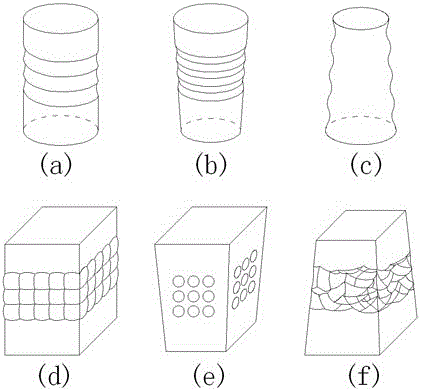
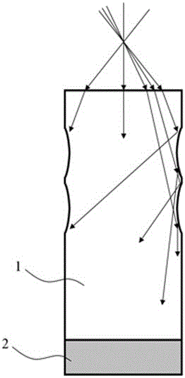
[0051] see Image 6 , the secondary concentrator adopts a cylindrical shape, the upper end of the side wall adopts a ring-shaped sawtooth groove, and the lower end adopts a smooth cylindrical surface. And irradiate the side wall, and the light irradiating each groove surface on the side wall can be regarded as an independent light source. Now take one of the groove surfaces for analysis, such as Image 6 The second groove surface on the left side of the center, the light irradiated on the groove surface becomes divergent light after reflection, and then converges to the bottom after multiple reflections on the side wall. It can be seen that the scattered light emitted by a single groove surface can be illuminates the entire battery surface. Although the uniformity of the light emitted by a single groove surface at the bottom cannot reach an ideal state, after the superposition of light reflected by multiple groove surfaces, a uniform light intensity distribution can finally ...
Embodiment 2
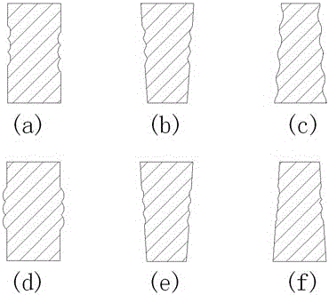
[0061] see Figure 7 , the secondary concentrator adopts a cylindrical shape, and the side walls adopt annular sawtooth grooves. Assume that by controlling the height of the concentrator, all light rays can only be reflected at most 3 times on the side wall. For incident light The range is still 0º~30º. Since the height of the groove part is greater than that of Example 1, the light irradiated on the groove part corresponds to The angular range will be larger, assuming 15º to 30º, and the rest of the light will be directly irradiated on the bottom of the concentrator.
[0062] According to the above formula, the relevant parameters can be substituted into:
[0063] ,
[0064] Consider the worst case, that is, the maximum angle between the normal direction and the horizontal direction of the surface of the groove part where the three reflection points are all place, namely: . exist is 30º, it can be obtained is 5.2º. Therefore, in order to ensure total reflect...
Embodiment 3
[0069] see Figure 8 , the secondary concentrator adopts the shape of a rounded table, and the side walls adopt ring-shaped sawtooth grooves, and the angle of the sawtooth is changed from the acute angle in Implementation 2 to a right angle or an obtuse angle, so as to facilitate the processing of the curved surface of the side wall. Note that it is necessary to Control the slope of the side wall of the circular frustum, that is, Figure 8 The included angle between the dotted line and the vertical direction is to avoid two or more consecutive reflections of light on the same side of the side wall.
[0070] Assume that by controlling the height of the concentrator, all light rays can only be reflected at most 3 times on the side wall. For incident light In the case where the range is still 0°~30°, the allowable range of the included angle between the surface normal direction and the horizontal direction of the groove part is the same as that in Embodiment 2, that is, 0°~5.2...
PUM
 Abstract
Description
Claims
Application Information
 - R&D
- Intellectual Property
- Life Sciences
- Materials
- Tech Scout
- Unparalleled Data Quality
- Higher Quality Content
- 60% Fewer Hallucinations
Browse by: Latest US Patents, China's latest patents, Technical Efficacy Thesaurus, Application Domain, Technology Topic, Popular Technical Reports.
© 2025 PatSnap. All rights reserved.Legal|Privacy policy|Modern Slavery Act Transparency Statement|Sitemap|About US| Contact US: help@patsnap.com


