Heat pump electric steam boiler

A steam boiler and heat pump technology, applied in the field of energy-saving heat pump electric steam boiler, can solve the problems of difficult high power output, high noise, low energy efficiency ratio, etc., and achieve the effect of eliminating boiler overpressure explosion

Inactive Publication Date: 2015-06-17
苟仲武
View PDF5 Cites 5 Cited by
  • Summary
  • Abstract
  • Description
  • Claims
  • Application Information

AI Technical Summary

Problems solved by technology

Therefore, the energy efficiency ratio of this combined heating is above 1.5, but its disadvantage is that the semiconductor heat pump is expensive and complicated to use, and the driving power must be DC.
However, the power of DC power supply equipment is small, so its cost is high, the technology is complicated, and it is difficult to output high power. There are certain problems in the implementation process.
[0005] In summary, the traditional electric, oil, and gas steam boilers on the market have a common disadvantage that the energy efficiency ratio is 1, it is impossible to use environmental energy, and cannot effectively use various waste water, factory sewage, environmental hot water, and solar water heaters in the environment. The hot water in the sewage, through the sewage source heat exchanger, brings the heat energy contained in the urban sewage of the building, and brings the heat energy in the soil, and the heat energy contained in the water of rivers and lakes through groundwater and ground wells.
However, the hybrid boiler using heat pump and traditional electric, oil, and gas heating has disadvantages such as low energy efficiency ratio, high cost, complicated use, and loud noise.
Moreover, the boilers in the prior art provide heat to heat water into steam. The heating method is simple and direct, and it is easy to make the internal pressure of the boiler continue to rise. The operator poses a great threat

Method used


Image

  • Heat pump electric steam boiler

Examples


Embodiment Construction

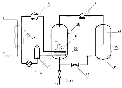
[0019] Attached below figure 1 The structure of the heat pump electric steam boiler of the present invention will be further described in detail.

[0020] Heat pump electric steam boiler of the present invention, please refer to figure 1 , which includes a heat exchange evaporator 3, a pressure vessel a8, and a pressure vessel b14.

[0021] The inside of the pressure vessel a8 is provided with a condensation heater 10, and the upper part of the heat exchange evaporator 3 is connected to the condensation heater 10 through a pipeline and a compressor 4. The bottom of the heat exchange evaporator 3 is connected to form a loop.

[0022] The top of the pressure vessel a8 is connected to the top of the pressure vessel b14 through a pipeline, a steam delivery pump 7 .

[0023] The bottom of the pressure vessel a8 is connected to the bottom of the pressure vessel b14 through a pipeline, a water return valve 12 , the bottom of the pressure vessel a8 is provided with a replenishment ...


PUM


Abstract

The invention discloses a heat pump electric steam boiler. The heat pump electric steam boiler comprises a heat exchange evaporator, a pressure container a and a pressure container b. As the heat pump technology is adopted in the heat pump electric steam boiler to serve as a sole heat source, energy in other media can be used, the energy efficiency ratio of the heat pump electric steam boiler is larger than the energy efficiency ratio of other boilers, large-proportion energy saving is achieved, and the larger energy saving, emission reduction and efficiency increase effect is obtained. In addition, as the temperature rise of a compressor condenser of a heat pump is limited, and continuous work will be stopped after the temperature reaches a certain ceiling temperature, explosion caused by unlimited rise cannot be caused, and explosion caused by continuous supply of the heat energy under the abnormal conditions of a prior boiler is avoided. Then steam separator is arranged in the heat pump electric steam boiler, so that the problem that water is contained in gas is solved. Finally, the lower temperature and the high temperature are separated, buffer space is provided, water replenishing is carried out in a lower temperature area, and therefore the pressure and temperature fluctuations can be avoided in the water replenishing process.

Description

technical field [0001] The invention relates to a heat pump steam boiler, in particular to an energy-saving heat pump electric steam boiler. Background technique [0002] Industrial boilers are the main thermal power equipment in China. The boiler industry is an eternal industry that coexists with human beings, especially in China, which is still a continuously developing industry. After the 1980s, China's economy has undergone rapid changes, the boiler industry has become more prominent, the number of boiler manufacturing enterprises in the country has increased by nearly one-half, and the ability to independently develop and develop new products generation after generation has been formed. approaching the level of developed countries. Boiler is an indispensable commodity in the era of economic development. How it will develop in the future is worth studying. [0003] A steam boiler refers to an industrial boiler that heats water to a certain parameter and produces high-t...

Claims


Application Information

Patent Timeline
IPC IPC(8): F22B1/16F25B30/02
Inventor 苟仲武
Owner 苟仲武
Why Eureka
Try Eureka