
Method and device for simulating optical link linearization

A route-based, one-way technology, applied in the field of microwave signal optical domain transmission

Inactive Publication Date: 2015-06-10
BEIJING UNIV OF POSTS & TELECOMM
View PDF4 Cites 13 Cited by
  • Summary
  • Abstract
  • Description
  • Claims
  • Application Information

AI Technical Summary

Problems solved by technology

[0004] Aiming at the defects of the prior art, the present invention provides a method and device for simulating the linearization of an optical link, which can overcome the need for highly coherent local oscillator signals and the need to precisely control polarization adjustment at the far end in existing coherent demodulation schemes. defect, which facilitates the long-distance transmission of radio frequency signals

Method used


Image

  • Method and device for simulating optical link linearization
  • Method and device for simulating optical link linearization
  • Method and device for simulating optical link linearization

Examples


Embodiment Construction

[0044] The following will clearly and completely describe the technical solutions in the embodiments of the present invention with reference to the accompanying drawings in the embodiments of the present invention. Obviously, the described embodiments are only some, not all, embodiments of the present invention. Based on the embodiments of the present invention, all other embodiments obtained by persons of ordinary skill in the art without making creative efforts belong to the protection scope of the present invention.

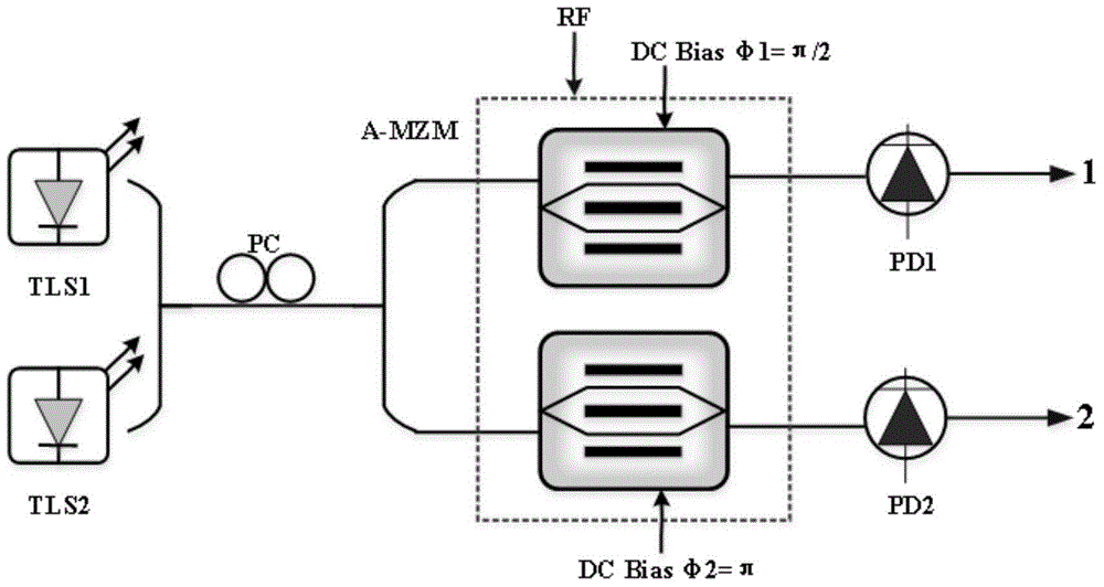
[0045] Such as figure 1 as shown, figure 1 A schematic structural diagram of a device for simulating optical link linearization provided by an embodiment of the present invention is shown, the device includes a laser 101, a first wavelength division multiplexer 102, a polarization modulator 103, a polarization controller 104, a detector A polarizer 105 , a second wavelength division multiplexer 106 , a first photodetector 107 and a second photodetector 108 . ...


PUM


Abstract

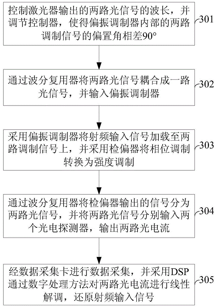
The invention provides a device for simulating optical link linearization. The device comprises a laser, a first wavelength division multiplexer, a polarization modulator, a polarization controller, a polarization analyzer, a second wavelength division multiplexer, a first photoelectric detector and a second photoelectric detector. The invention further provides a method for simulating optical link linearization. According to the method, the polarization modulator and the polarization analyzer are equivalent to an asymmetric Mach-Zehnder modulator, analog signal strength is orthogonally modulated on a pair of simultaneously propagating optical links, the difference between offsetting angles of the two modulators is 90 degrees, and original analog signals are linearly restored at a far end by the aid of direct detection of the two links and digital signal processing technology. Demodulated signals cannot be intensively interfered by delay mismatching problems caused by double parallel structures, stability of a system is enhanced, highly coherent intrinsic signals are omitted, accurate polarization adjustment at the far end is omitted, and long-distance transmission of radio frequency signals is benefited.

Description

technical field [0001] The invention relates to the technical field of microwave signal optical domain transmission, in particular to a method and device for simulating the linearization of an optical link. Background technique [0002] In recent years, the analog optical link using optical fiber as the radio frequency signal transmission medium has made long-distance transmission of radio frequency signals possible due to its outstanding advantages in quality, volume, and power loss. In addition, the analog optical link has obvious anti-electromagnetic interference characteristics, can transmit and process multiple different radio frequency signals at the same time, has strong flexibility, and has important application value in civil communication and military fields. In the analog optical link, the most important core is to develop a high linearization scheme, suppress third-order intermodulation distortion, improve the dynamic range of the entire link, and further meet th...

Claims


Application Information

Patent Timeline
IPC IPC(8): H04B10/2575
Inventor 戴一堂徐坤宁婕妤尹飞飞李建强
Owner BEIJING UNIV OF POSTS & TELECOMM
Learn More