Inductance element and method for manufacturing inductance element
A technology of inductive components and manufacturing methods, which is applied in the direction of electrical components, transformer/inductor parts, coil manufacturing, etc., can solve problems such as short circuits at terminals, achieve the effects of preventing short circuits, maintaining welding strength, and preventing deterioration
Active Publication Date: 2015-06-10
ALPS ALPINE CO LTD
View PDF8 Cites 15 Cited by
- Summary
- Abstract
- Description
- Claims
- Application Information
AI Technical Summary
Problems solved by technology
[0005] However, if a surface electrode layer mainly composed of Ag is formed on the surface of the terminal portion as in the coil-enclosed powder core body described in Patent Document 1, when the core bodies are mounted close to each other on the mounting substrate, or with When other electronic components are mounted close to each other, when the coil and the terminal are energized, the Ag contained in the surface electrode layer is exposed due to the action of the battery, and there is a possibility of a short circuit between adjacent terminals due to the exposed Ag.
Method used
View moreImage
Smart ImageViewing Examples
Examples
Embodiment 1
[0084] (Example 1) Cu substrate / base layer / surface electrode layer: Ag (thickness 1.0~1.3 μm), no accelerated aging
Embodiment 2
[0085] (Example 2) Cu base material / base layer / surface electrode layer: Ag (thickness 0.2~0.3 μ m), no accelerated aging
Embodiment 3
[0086] (Example 3) Cu substrate / base layer / surface electrode layer: Ag (thickness 1.0-1.3 μm), accelerated aging
Login to View More PUM
| Property | Measurement | Unit |
|---|---|---|
| thickness | aaaaa | aaaaa |
| thickness | aaaaa | aaaaa |
| thickness | aaaaa | aaaaa |
Abstract
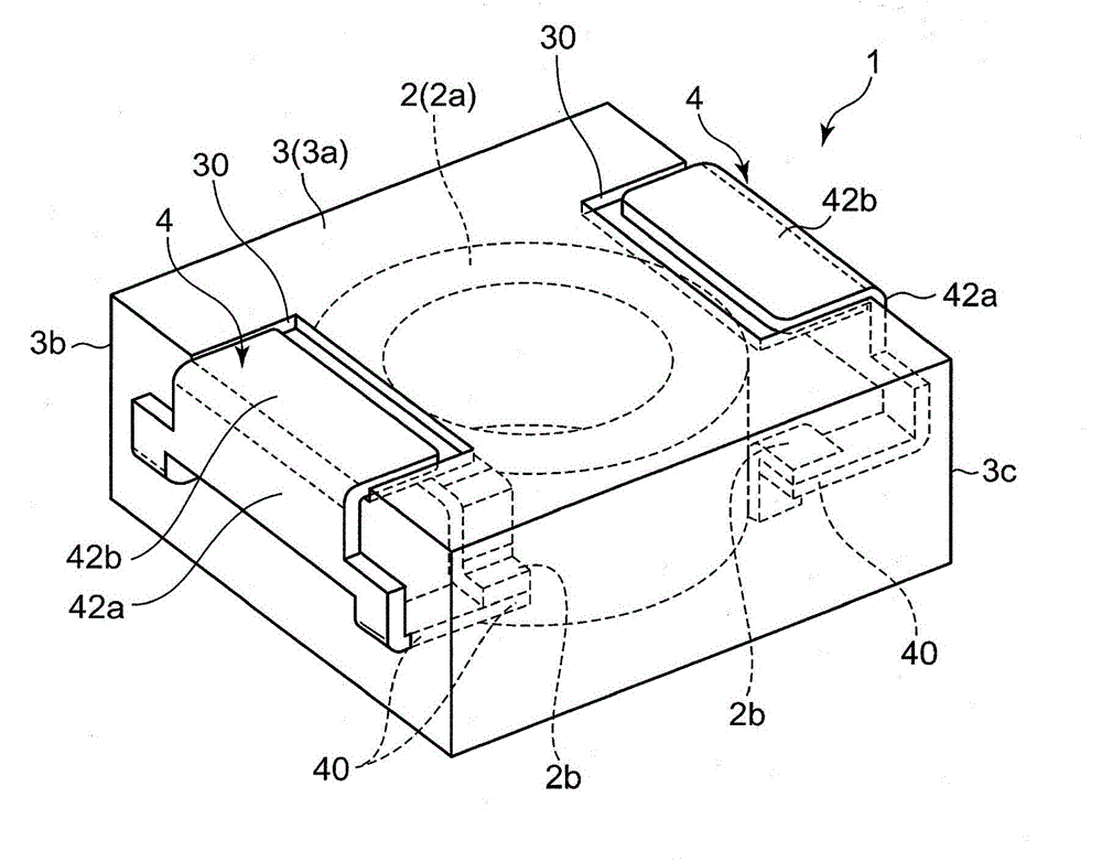
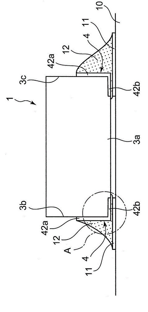
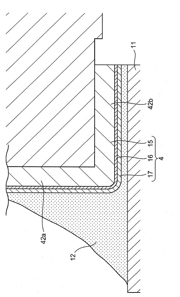
The invention provides an inductance element and a method for manufacturing the inductance element. The inductance element can prevent short circuit even though the inductance element gets close to an inductance element which contains Ag on a surface electrode layer on an installing substrate. The inductance element comprises a press powder core body, a coil buried in the press powder core body, and a terminal portion electrically connected with the coil through welding. The terminal portion comprises a Cu base material and a surface electrode layer formed on the surface of the Cu base material. The surface electrode layer is formed by Ag or alloy of Ag. The terminal portion comprises a solder joint portion which is joined with a welding portion welded on the coil relative to the installing substrate by a solder. The thickness of the side of the surface electrode layer which is provided with the welding portion is thicker than the thickness of the side of the solder joint portion.
Description
technical field [0001] The present invention relates to an inductance element in which a coil is embedded in a magnetic core and a manufacturing method thereof. Background technique [0002] Patent Document 1 discloses an invention related to a coil-encapsulated compressed powder core. The coil-enclosed dust core has a dust core, a coil covering the dust core, and a terminal portion electrically connected to the coil. The dust core is formed of magnetic powder of Fe-based amorphous alloy and binder resin. Both the coil and the terminal portion are formed of a Cu (copper) base material. Surface treatment by plating is applied to the terminal part for soldering with an external circuit. [0003] In order to improve the magnetic properties of the powder core body formed of the magnetic powder of the Fe-based amorphous alloy and the binder resin, heat treatment is preferably performed after molding, so the metal used for the surface treatment of the terminal part needs to be ...
Claims
Login to View More Application Information
Patent Timeline
 Patent Type & Authority Applications(China)
IPC IPC(8): H01F27/29H01F41/10
CPCH01F17/04H01F27/255H01F27/29H01F41/04H01F41/10
Inventor 佐藤昭
Owner ALPS ALPINE CO LTD
Features
- R&D
- Intellectual Property
- Life Sciences
- Materials
- Tech Scout
- Unparalleled Data Quality
- Higher Quality Content
- 60% Fewer Hallucinations
Learn More Browse by: Latest US Patents, China's latest patents, Technical Efficacy Thesaurus, Application Domain, Technology Topic, Popular Technical Reports.
© 2025 PatSnap. All rights reserved.Legal|Privacy policy|Modern Slavery Act Transparency Statement|Sitemap|About US| Contact US: help@patsnap.com


