
Process for machining heat exchange device of heat exchanger

A technology of processing technology and heat exchange device, applied in the field of mechanical processing and manufacturing, can solve problems such as tube sheet deformation, crevice corrosion at welds, easy pulling, etc., to achieve quality and reliability improvement, strength and stiffness guarantee, and simplify processing procedures Effect

Active Publication Date: 2015-06-10
SICHUAN BLUSR MACHINERY
View PDF9 Cites 5 Cited by
  • Summary
  • Abstract
  • Description
  • Claims
  • Application Information

AI Technical Summary

Problems solved by technology

[0004] However, since the weld seam is set on the tube sheet, a gap is likely to appear between the heat exchange tube and the tube sheet at the weld seam, so crevice corrosion is prone to occur at the weld seam; The repeated occurrence of high temperature in multiple parts above makes the internal stress of the tube sheet complex, stress concentration occurs, and it is easy to cause deformation of the tube sheet, which reduces the fatigue strength, corrosion resistance, high temperature resistance and high pressure resistance of the tube sheet. During the welding process, it is easy to pull the previously welded joints, causing the previously welded joints to be cracked, which further reduces the reliability of the joints; in addition, due to the large number of welds on the tube sheet and the There are several heat exchange tubes on the side, so it is not convenient to perform flaw detection on these welds, and it further increases the difficulty of manufacturing the heat exchange device

Method used


Image

  • Process for machining heat exchange device of heat exchanger
  • Process for machining heat exchange device of heat exchanger
  • Process for machining heat exchange device of heat exchanger

Examples


specific Embodiment

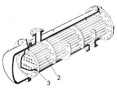
[0036] Adopt processing technology of the present invention to manufacture the heat exchanging device (as figure 1shown), the specific process is as follows:

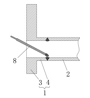
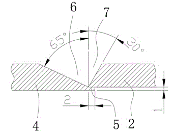
[0037] (1) Subsection manufacturing: Subsection manufacturing is carried out according to the design structure of the heat exchange device. The subsection manufacturing components include: a tube base 1 and several heat exchange tubes 2 connected to the tube base 1, and the tube base 1 includes a tube plate 3 and several joints 4 corresponding to the heat exchange tubes 2, the joints 4 and the tube plate 3 are integrally structured, and the The end is provided with an annular step 5, the thickness of the annular step 5 is 1 mm, the length of the annular step 5 is 2 mm, and the inner wall of the annular step 5 matches the outer wall of the heat exchange tube 2 , the inner wall of the joint 4 and the junction of the annular step 5 are also provided with a first groove 6, and the end of the heat exchange tube 2 that coope...


PUM

PropertyMeasurementUnit
thicknessaaaaaaaaaa
lengthaaaaaaaaaa

Abstract

The invention relates to the field of mechanical machining and manufacturing, in particular to a process for machining a heat exchange device of a heat exchanger. The process is characterized by comprising the following steps in sequence: (1) section manufacturing, to be specific, the section manufacturing is performed according to a design structure of a heat exchange device, wherein the components for section manufacturing comprise a tube base and several heat exchange tubes connected with the tube base, the tube base comprises a tube plate and several joints corresponding to the heat exchange tubes, and the joints are integrated with the tube plate; (2) connection of the joints and the heat exchange tubes, to be specific, the several heat exchange tubes are welded with the corresponding joints respectively, the heat exchange device of a heat exchanger is obtained after welding all the components. With adoption of the process, the machining procedure of the heat exchange device can be simplified greatly, the machining cost can be reduced, and the quality and reliability of the obtained heat exchange device are also improved greatly.

Description

technical field [0001] The invention relates to the field of mechanical processing and manufacturing, in particular to a processing technology of a heat exchange device of a heat exchanger. Background technique [0002] Heat exchanger is a common equipment for heat exchange, widely used in chemical industry, petroleum, petrochemical, electric power, light industry, metallurgy, atomic energy, shipbuilding, aviation, heating and other industries. Tube-and-tube heat exchangers are widely used due to their strong structure, high reliability, large adaptability, and wide range of materials. The structure mainly includes a shell and a heat exchange device installed in the shell. It includes several heat exchange tubes and tube sheets arranged at both ends of the heat exchange tubes. Due to the large number of heat exchange tubes, the connection between the heat exchange tubes and the tube sheets becomes the most cumbersome process in the heat exchanger manufacturing process; and, ...

Claims


Application Information

Patent Timeline
Patent Type & Authority Applications(China)
IPC IPC(8): B23P15/26B23K31/02B23K33/00B23K101/14
CPCB23K31/003B23K31/02B23K33/00B23K2101/14B23P15/26
Inventor 陈浩李文杰李华
Owner SICHUAN BLUSR MACHINERY
Learn More