RC pre-amplifying circuit

A preamplifier and circuit technology, applied in the direction of negative feedback circuit layout, improving the amplifier to reduce the impact of noise, etc., can solve the problems of signal error, increase the design cost, reduce the signal-to-noise ratio of the circuit, etc., to improve the phase margin, expand the Broadband, small size effect

Inactive Publication Date: 2015-06-03
GUANGXI NORMAL UNIV
View PDF2 Cites 1 Cited by
  • Summary
  • Abstract
  • Description
  • Claims
  • Application Information

AI Technical Summary

Problems solved by technology

One is to connect a few kΩ resistor to the ground at the output end of the receiving sensor. This method of connecting a fixed load will have a higher signal-to-noise ratio at low frequencies, but at medium and high frequencies, the load is a resistor, and the received signal is The internal resistance changes with the frequency, which is very likely to cause the internal resistance of the received signal to be equal to or smaller than the load resistance, thereby reducing the signal-to-noise ratio of the entire circuit. In addition, the load of a few kΩ resistors pulled down to the ground, in the middle and high When the frequency is amplified, the thermal noise of the load resistor is likely to be at the same level as the noise density of the amplifier, which will also cause an additional error in the overall signal
The other is to replace the above-mentioned several kΩ ground load with an additional level of integrated operational amplifier. Although it can solve the problem of high input impedance, it requires an additional integrated operational amplifier chip, which will increase the overall design cost.

Method used


Image

  • RC pre-amplifying circuit
  • RC pre-amplifying circuit
  • RC pre-amplifying circuit

Examples


Embodiment Construction

[0025] In order to understand the above-mentioned purpose, features and advantages of the present invention more clearly, the present invention will be further described in detail below in conjunction with the accompanying drawings and specific embodiments. It should be noted that, in the case of no conflict, the embodiments of the present application and the features in the embodiments can be combined with each other.

[0026] In the following description, many specific details are set forth in order to fully understand the present invention. However, the present invention can also be implemented in other ways different from those described here. Therefore, the protection scope of the present invention is not limited by the specific details disclosed below. EXAMPLE LIMITATIONS.

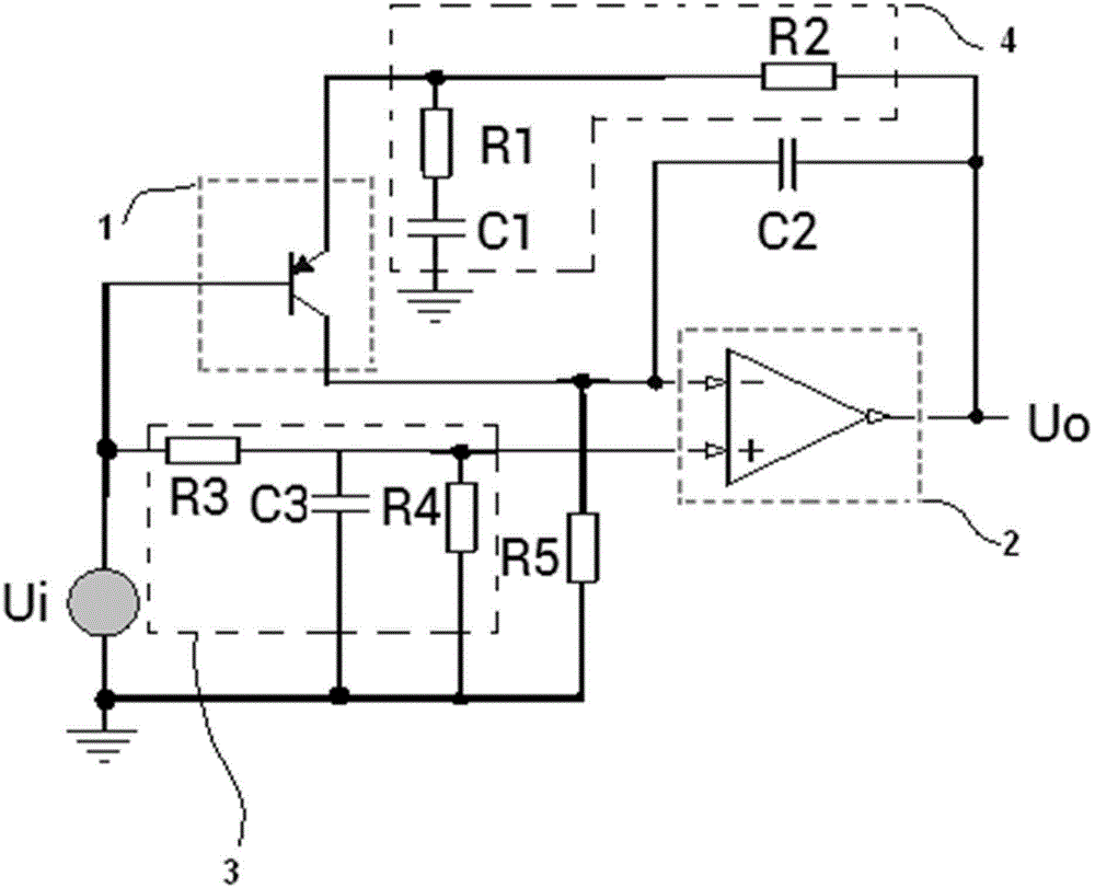
[0027] Combine below figure 1 , specifically describe the RC preamplifier circuit according to the embodiment of the present invention.

[0028] Such as figure 1 As shown, the RC preamplifier circ...


PUM

PropertyMeasurementUnit
Resistanceaaaaaaaaaa
Resistance rangeaaaaaaaaaa
Capacitanceaaaaaaaaaa

Abstract

The invention provides a RC pre-amplifying circuit comprising a signal source Ui, a first cascade transistor, a second cascade amplifier, a bootstrap circuit, a load resistor R5, a miller capacitor C2 and a cascade negative feedback circuit. The base electrode of the first cascade transistor is connected to the input end of the signal source Ui, the emitting electrode is connected to the input end of the cascade negative feedback circuit which is connected to the output end of the second cascade amplifier, the collecting electrode of the first cascade transistor is connected to one end of the load resistor R5 and the negative input end of the second cascade amplifier, and the other end of the load resistor R5 is grounded, the output end of the second cascade amplifier serves as a signal output end; two ends of the miller capacitor C2 are connected to the negative input end and output end of the second cascade amplifier, and the bootstrap circuit is connected between the positive input end of the second cascade amplifier and the positive end of the signal source Ui. The RC pre-amplifying circuit is simple in structure, small in size and low in cost, and the stability is same as that of a dual operational amplifying circuit.

Description

technical field [0001] The invention relates to a sensor receiving circuit, in particular to an RC preamplifier circuit with high impedance input. Background technique [0002] In the sensor receiving circuit, piezoelectric receiving sensors can measure dynamic force, mechanical shock and vibration, and are widely used in acoustics, medicine, mechanics, navigation, etc. However, the internal resistance equivalent model of this type of receiving sensing is composed of resistance, capacitance and inductance, and its impedance is relatively large and changes with frequency. In addition, the signal received by the general sensor is very weak. When a weak signal is amplified to a level that can be detected, a preamplifier circuit is required. If the piezoelectric receiving sensor directly uses the existing Sallen-Key amplifier circuit or multiple feedback amplifier circuit (Multiple Feedback) as its preamplifier circuit, there will be a problem that the internal resistance of th...

Claims


Application Information

Patent Timeline
IPC IPC(8): H03F1/26H03F1/34
Inventor 秦运柏肖琨宋树祥雷晓平丘森辉唐荣江谢军涛蒋品群
Owner GUANGXI NORMAL UNIV
Why Eureka
Try Eureka