
Permanent magnet synchronous reluctance motor and compressor

A synchronous reluctance motor and permanent magnet type technology, which is applied to synchronous machines, synchronous motors with stationary armatures and rotating magnets, magnetic circuits, etc., can solve the problem that the reluctance torque cannot effectively compensate for the permanent magnet torque, and the motor Reduced no-load back EMF, unsatisfactory improvement of motor efficiency, etc., to achieve the effect of reducing current, increasing total torque, and improving efficiency

Inactive Publication Date: 2015-06-03
GUANGDONG MEIZHI COMPRESSOR +1
View PDF4 Cites 4 Cited by
  • Summary
  • Abstract
  • Description
  • Claims
  • Application Information

AI Technical Summary

Problems solved by technology

[0005] In the aforementioned patents, although the motor increases the reluctance torque by increasing the difference between the AC and direct axis reactance, it will lead to a decrease in the no-load back EMF of the motor, and the increase in the reluctance torque cannot effectively compensate for the decrease in the permanent magnet torque. , so the total output torque of the motor will decrease, and the efficiency improvement of the motor is not ideal

Method used


Image

  • Permanent magnet synchronous reluctance motor and compressor
  • Permanent magnet synchronous reluctance motor and compressor
  • Permanent magnet synchronous reluctance motor and compressor

Examples


Embodiment Construction

[0035] Embodiments of the present invention are described in detail below, examples of which are shown in the drawings, wherein the same or similar reference numerals designate the same or similar elements or elements having the same or similar functions throughout. The embodiments described below by referring to the figures are exemplary and are intended to explain the present invention and should not be construed as limiting the present invention.

[0036] In describing the present invention, it is to be understood that the terms "center", "length", "width", "thickness", "inner", "outer", "axial", "radial", "circumferential ” and other indicated orientations or positional relationships are based on the orientations or positional relationships shown in the accompanying drawings, which are only for the convenience of describing the present invention and simplifying the description, rather than indicating or implying that the referred device or element must have a specific orien...


PUM


Abstract

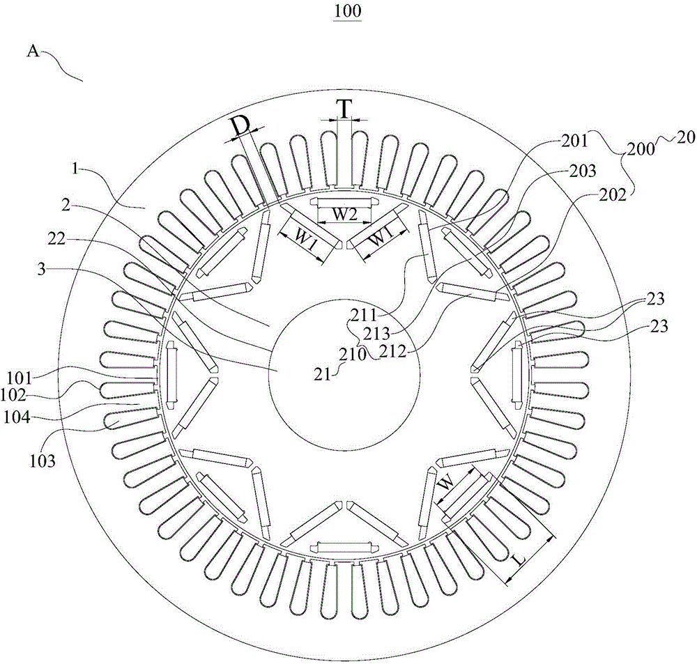
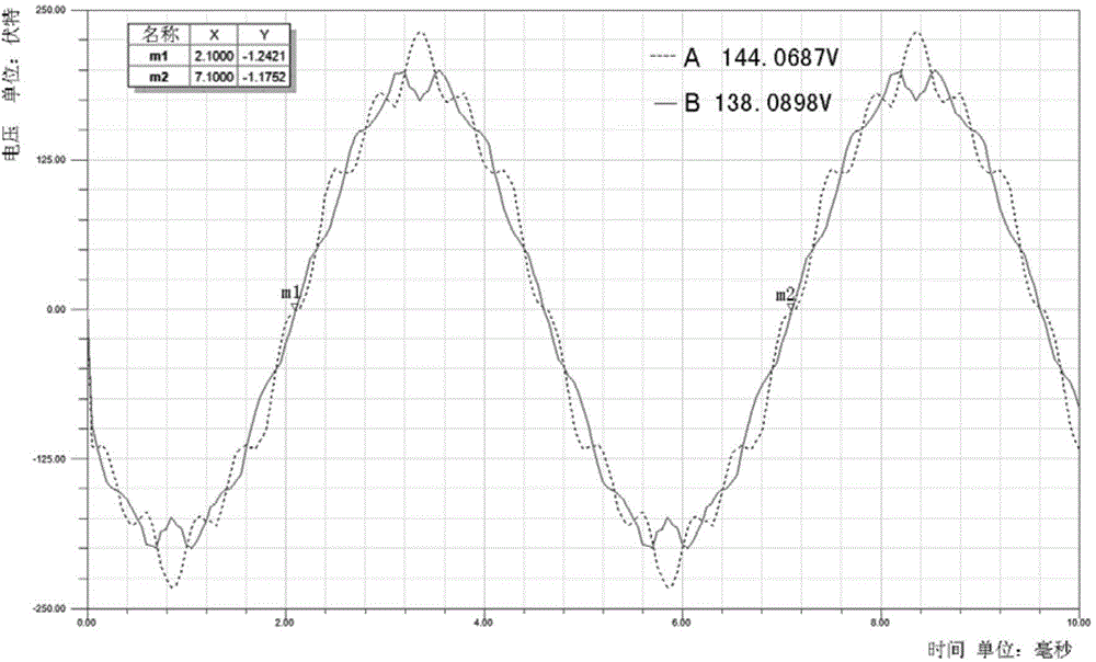
The invention discloses a permanent magnet synchronous reluctance motor and a compressor. The permanent magnet synchronous reluctance motor comprises a stator and a rotor, wherein the stator comprises a stator inner hole and a plurality of stator slots; a stator tooth is defined between every two adjacent stator slots; the rotor is arranged inside the stator inner hole; the rotor comprises a rotor inner hole and multiple mounting slot groups; a permanent magnet is arranged inside each mounting slot group; the width of each stator tooth is T; the shortest distance between each two adjacent mounting slot groups is D, and the ratio of D to T is greater than 0.8 and smaller than 1. According to the permanent magnet synchronous reluctance motor, the reluctance torque can be increased, and at the same time, the permanent magnet torque keeps unchanged or is slightly lowered, so that the total torque generated by the unit current of the motor is increased and the efficiency of the motor is improved; when the total torque output by the motor is unchanged, the input current of the stator can be reduced, the power density of the motor can be increased and the using amount of the permanent magnet can be reduced, so that the cost of the motor is lowered. Furthermore, the compressor with the motor has relatively high APF energy efficiency.

Description

technical field [0001] The invention relates to the field of motors, in particular to a permanent magnet synchronous reluctance motor and a compressor. Background technique [0002] At present, in order to improve the output torque and efficiency of the motor, in the motor made of high magnetic permeability material, there are generally multiple sets of permanent magnets embedded in the rotor core, and each set of permanent magnet slots includes multiple radial or Tangentially arranged permanent magnet slots, this type of motor has the characteristics of making full use of the reluctance torque to improve the output torque and efficiency of the motor. [0003] The open specification of the Chinese patent CN10405227A discloses a permanent magnet synchronous reluctance motor. In order to obtain a higher output torque, the above-mentioned patent has innovated the arrangement and setting parameters of the permanent magnets in the rotor core. [0004] But from the electromagneti...

Claims


Application Information

Patent Timeline
IPC IPC(8): H02K29/00H02K29/03H02K1/27H02K21/14
CPCH02K29/00H02K1/2713H02K1/274H02K21/145H02K29/03
Inventor 于明湖杨泾涛
Owner GUANGDONG MEIZHI COMPRESSOR
Learn More