A pump truck hydraulic system and pump truck

A technology of hydraulic system and pumping system, applied in the direction of fluid pressure actuating device, servo motor, servo meter circuit, etc., can solve the problems of waste of energy consumption, idle oil pump, interruption, etc., to reduce energy consumption and avoid loss of lost work. Effect

Active Publication Date: 2017-08-04
河北雷萨重型工程机械有限责任公司
View PDF5 Cites 0 Cited by
  • Summary
  • Abstract
  • Description
  • Claims
  • Application Information

AI Technical Summary

Problems solved by technology

[0005] In the above-mentioned prior art, there must be a working condition where a certain oil pump is idle, resulting in waste of energy consumption
Moreover, in actual work, when a certain oil pump fails, one of the two systems must fail to work and cause construction interruption.

Method used


Image

  • A pump truck hydraulic system and pump truck
  • A pump truck hydraulic system and pump truck
  • A pump truck hydraulic system and pump truck

Examples


Embodiment Construction

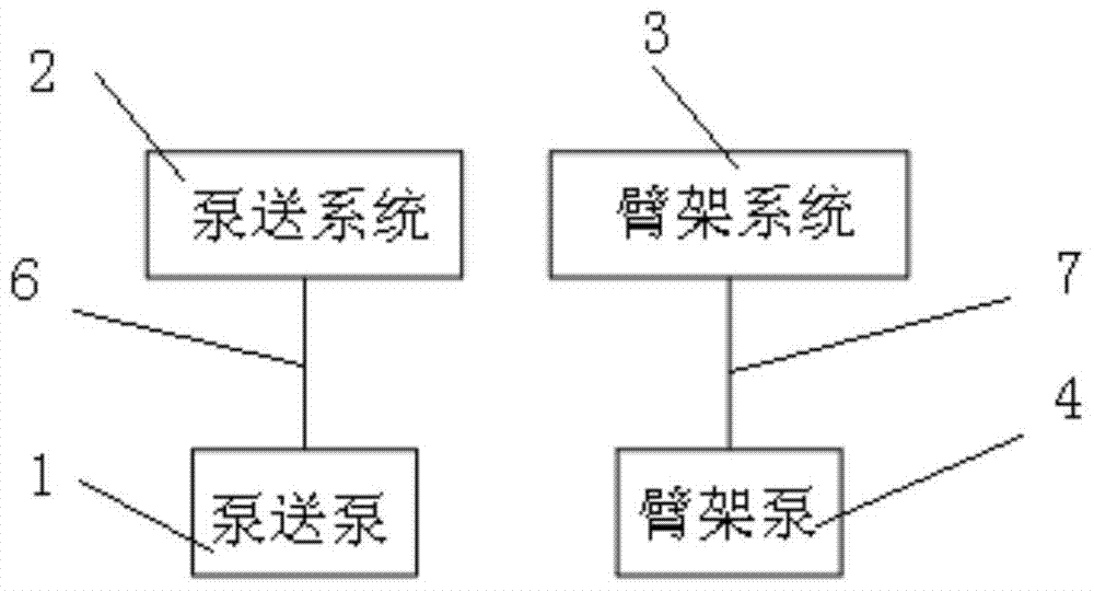
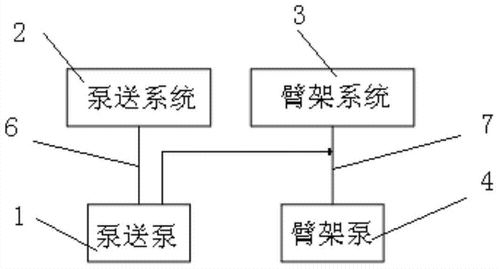
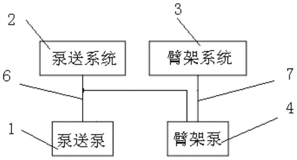
[0026] In order to make the objectives, technical solutions and advantages of the present invention clearer, the technical solutions in the embodiments of the present invention will be described in more detail below in conjunction with the drawings in the embodiments of the present invention. In the drawings, the same or similar reference numerals denote the same or similar elements or elements having the same or similar functions throughout. The described embodiments are some, but not all, embodiments of the invention. The embodiments described below by referring to the figures are exemplary and are intended to explain the present invention and should not be construed as limiting the present invention. Based on the embodiments of the present invention, all other embodiments obtained by persons of ordinary skill in the art without creative efforts fall within the protection scope of the present invention. Embodiments of the present invention will be described in detail below ...


PUM


Abstract

The invention discloses a pump truck hydraulic system and a pump truck. The pump truck comprises a pump truck hydraulic system. The pump truck hydraulic system comprises a boom pump, a pumping pump and a control valve group, is communicated with a boom liquid supply pipeline and a pumping liquid supply pipeline and can be switched between the pumping liquid supply state and the boom liquid supply state, wherein the control valve group enables the boom liquid supply pipeline to be communicated with the pumping liquid supply pipeline in one way in the pumping liquid supply state to allow the boom pump to supply hydraulic liquid to the pumping system; in the boom liquid supply state, the control valve group enables the pumping liquid supply pipeline to be communicated with the boom liquid supply pipeline in one way to allow the pumping pump to provide hydraulic liquid for the boom system. The pump truck hydraulic system achieves the following function that two pumps can supply liquid to one system together on the same pump truck and can also conduct liquid supply work independently. Compared with the prior art, the energy consumption can be reduced to the largest extent, and missed working time caused by damage to the single pump is avoided.

Description

technical field [0001] The invention relates to the technical field of engineering machinery, in particular to a pump truck hydraulic system in which a boom and pumping supply fluid to each other, and the pump truck hydraulic system is mainly used for concrete conveying machinery products with a distribution boom. Background technique [0002] figure 1 It is a schematic diagram of a pump truck hydraulic system in the prior art. exist figure 1 In the hydraulic system of the pump truck shown, both the boom hydraulic system 3 and the pumping system 2 are driven by their own independent power pumps (boom pump 4 and pumping pump 1). [0003] figure 2 It is a schematic diagram of another pump truck hydraulic system in the prior art. exist figure 2 In the hydraulic system of the pump truck shown, the boom hydraulic system 3 can be driven by the boom pump 4 and the pumping pump 1 at the same time, and the pumping system 2 is driven by the pumping pump 1 alone. [0004] ima...

Claims


Application Information

Patent Timeline
Patent Type & Authority Patents(China)
IPC IPC(8): F15B11/17F15B13/02E04G21/02
CPCE04G21/02F15B11/17F15B13/02F15B2211/20576
Inventor 刘震捷张华刘明清
Owner 河北雷萨重型工程机械有限责任公司
Why Eureka
Try Eureka