
Workpiece laser automatic repair method

A repair method and workpiece technology, applied in the field of laser repair, can solve the problems of low repair quality and precision, laser cladding track generation, low repair efficiency of net shape repair system, etc., to avoid roughness, reduce generation time, time-saving effect

Inactive Publication Date: 2015-06-03
NANJING HUIRUI PHOTOELECTRIC TECH CO LTD
View PDF3 Cites 40 Cited by
  • Summary
  • Abstract
  • Description
  • Claims
  • Application Information

AI Technical Summary

Problems solved by technology

[0008] The purpose of the present invention is to provide an automatic repair method in order to overcome the defects in the above-mentioned prior art, to solve the problems of low repair efficiency and low repair quality and precision of the net shape repair system in the prior art, thereby improving production efficiency , save time and cost, realize mass production and processing, and complete automatic repair of workpieces
The invention focuses on solving the problems of three-dimensional surface scanning, image processing, and laser cladding trajectory generation

Method used


Image

  • Workpiece laser automatic repair method
  • Workpiece laser automatic repair method
  • Workpiece laser automatic repair method

Examples


Embodiment Construction

[0028] The present invention will be described in detail below in conjunction with the accompanying drawings and specific embodiments. This embodiment is carried out on the premise of the technical solution of the present invention, and detailed implementation and specific operation process are given, but the protection scope of the present invention is not limited to the following embodiments.

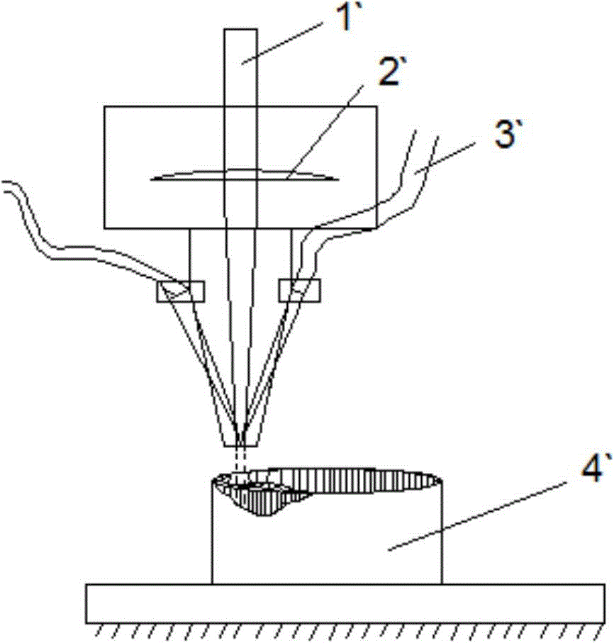
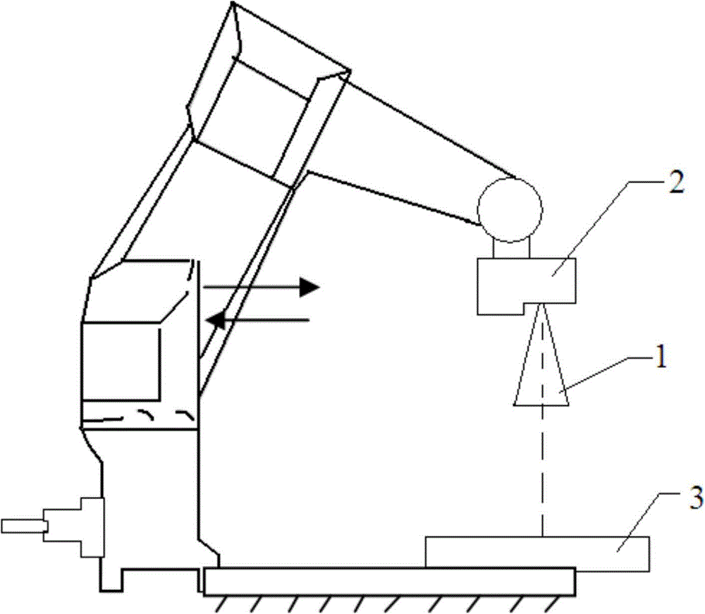
[0029] A laser automatic repair method for a workpiece, firstly detects the shape of the workpiece (i.e. three-dimensional surface scanning), and automatically generates a laser repair track, thereby achieving automatic repair of the workpiece; Effect. The function of automatic generation of repair trajectory mainly includes 3D surface scanning, image processing, filling and other technologies. Such as figure 2 As shown, the method specifically includes the following steps:

[0030] 1) The laser 3D scanner scans the three-dimensional surface of the workpiece online to obtain the s...


PUM


Abstract

The invention relates to a workpiece laser automatic repair method which comprises the following steps: 1) carrying out three-dimensional molding surface on-line scanning on the workpiece by a laser 3D scanner to obtain spatial sampling points on the workpiece surface, namely three-dimensional point cloud data; 2) carrying out coordinate transformation on the spatial sampling points obtained by scanning, and reconstructing a three-dimensional workpiece surface point set in a repair actuating mechanism coordinate system; 3) carrying out image processing on the point cloud data obtained in the step 1), and extracting boundary contour of the workpiece; 4) generating a laser cladding trajectory according to the boundary contour of the workpiece; 5) converting the laser cladding trajectory into machine recognition codes, and storing in a repair actuating mechanism; and 6) carrying out automatic repair on the workpiece according to the laser cladding trajectory by the repair actuating mechanism. Compared with the prior art, the method enhances the production efficiency, saves the time cost, implements mass production and the like.

Description

technical field [0001] The invention relates to a laser repair method, in particular to a laser automatic repair method for workpieces. Background technique [0002] There are a large number of high-performance, high-value-added metal parts in industrial products that need to be repaired, such as turbine blades of gas turbines and aircraft engines, oil drilling tools, injection molding or stamping dies, rolls, knives, etc. The key components of these high-performance materials are often the weak links that determine the life cycle life of the entire machine equipment. Using advanced detection and repair technology to automatically repair defective and damaged parts, so that they can meet the requirements of industrial equipment and prolong their service life, can obtain considerable technical and economic benefits. Taking the turbine blade as an example, due to its harsh working environment, the material used is often a nickel-based superalloy with excellent performance. Th...

Claims


Application Information

Patent Timeline
IPC IPC(8): C23C24/10
CPCB23P6/002B23K26/032B23K26/0884B23K26/144B23K26/147B23K26/34B23K2101/001B23K2103/26F01D5/005F05D2230/31
Inventor 杨艳齐欢
Owner NANJING HUIRUI PHOTOELECTRIC TECH CO LTD
Learn More