Storage element, storage apparatus, and magnetic head

A technology for storage elements and storage layers, applied in magnetic recording heads, electrical components, information storage, etc., can solve the problems of storage element current limitation, achieve stable operation, improve thermal stability, and promote the effect of increasing storage capacity

Inactive Publication Date: 2015-05-27
SONY CORP
View PDF8 Cites 7 Cited by
  • Summary
  • Abstract
  • Description
  • Claims
  • Application Information

AI Technical Summary

Problems solved by technology

[0035] Also, if a tunnel insulating layer is used in the interlayer as an MTJ structure, there is a limit to the amount of current supplied to the memory element in order to prevent dielectric breakdown of the tunnel insulating layer.

Method used


Image

  • Storage element, storage apparatus, and magnetic head
  • Storage element, storage apparatus, and magnetic head
  • Storage element, storage apparatus, and magnetic head

Examples


Embodiment Construction

[0068] Hereinafter, preferred embodiments of the present disclosure will be described in detail with reference to the accompanying drawings. It should be noted that, in this specification and the accompanying drawings, structural elements that have the same function and structure are denoted with the same reference numerals, and description of these structural elements will not be repeated.

[0069] Embodiments of the present disclosure are described in the order indicated below.

[0070] 1. Overall configuration of the storage device according to the embodiment

[0071] 2. Outline of the memory element according to the embodiment

[0072] 3. Examples and Experimental Results

[0073] 4. Variations

[0074] 1. Overall configuration of the storage device according to the embodiment

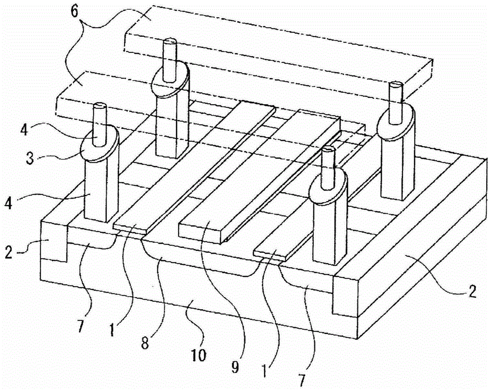
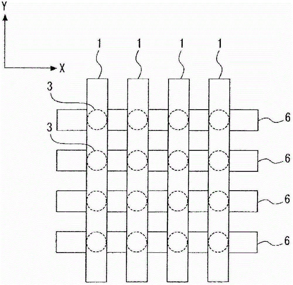
[0075] First, the overall configuration of the storage device will be described. Figure 1 to Figure 3 A schematic diagram of the storage device is shown in . figure 1 is perspective, figur...


PUM


Abstract

There is provided a storage element including a layered construction including a storage layer that has magnetization perpendicular to a surface of the storage layer and whose direction of magnetization is changed corresponding to information, a pinned magnetization layer that has magnetization perpendicular to a surface of the pinned magnetization layer and serves as a standard for information stored in the storage layer, and an insulating layer that is composed of a non-magnetic material and is provided between the storage layer and the pinned magnetization layer.

Description

technical field [0001] The present disclosure relates to a memory element and a memory device including a plurality of magnetic layers and recording data using spin torque magnetization reversal. [0002] The present disclosure also relates to magnetic heads that detect magnetic signals from magnetic recording media. [0003] The present disclosure contains subject matter disclosed in Japanese Priority Patent Application JP 2012-217702 filed in the Japan Patent Office on Sep. 28, 2012, the entire content of which is hereby incorporated by reference. [0004] reference list [0005] patent documents [0006] PTL 1: JP 2003-17782A [0007] PTL 2: USP 6,256,223 [0008] PTL 3: JP 2008-227388A [0009] non-patent literature [0010] NPL 1: Phys. Rev. B, 54, 9353 (1996) [0011] NPL 2: J. Magn. Mat., 159, L1 (1996) [0012] NPL 3: Nature Materials., 5, 210 (2006) [0013] NPL 4: Phys. Rev. Lett., 67, 3598 (1991) Background technique [0014] With the rapid development o...

Claims


Application Information

Patent Timeline
Patent Type & Authority Applications(China)
IPC IPC(8): H01L43/08G11C11/16B82Y25/00
CPCB82Y25/00G11B5/3909G11C11/161G11B5/3906H01F10/123H01F10/3272H01F10/3286H01F10/329H10B61/22H10N50/10H10N50/85H10B61/00H10N50/80G11B5/1278G11B5/3146H01L23/528
Inventor 山根一阳细见政功大森广之别所和宏肥后丰浅山徹哉内田裕行
Owner SONY CORP
Why Eureka
Try Eureka