
Micro power digital pressure gauge and pressure measuring method

A pressure gauge and micro-power consumption technology, which is applied in the direction of fluid pressure measurement by changing ohmic resistance, can solve the problems of inability to use overpressure, decreased measurement accuracy, short service life, etc., and achieves strong overpressure capability and good reliability. , the effect of high sensitivity

Active Publication Date: 2015-05-27
无锡市特种压力表有限公司
View PDF4 Cites 3 Cited by
  • Summary
  • Abstract
  • Description
  • Claims
  • Application Information

AI Technical Summary

Problems solved by technology

[0003] The traditional mechanical pressure gauge is limited by its structure. The pointer reading can only be used to estimate the reading. The error is large, which reduces the measurement accuracy. It cannot be used with overpressure. The mechanical parts are prone to fatigue and the service life is short, requiring regular professionals. Only maintenance can ensure its reliability, which virtually increases the cost
[0004] For pressure transmitters, it is mainly used in occasions that require remote transmission of pressure values. Although it has a digital tube or liquid crystal display, the 4~20mA signal output by the transmitter can only be transmitted to the central control room through cables. The upper computer in the control room converts and displays the pressure value, so in the actual site, the staff often cannot grasp the real-time pressure value immediately
In addition, the pressure transmitter needs an external DC power supply to power it when it is working, so it is not suitable for some occasions where the transmission output is not required and the laying of the line is not convenient, and it is largely restricted by the site conditions.

Method used


Image

  • Micro power digital pressure gauge and pressure measuring method
  • Micro power digital pressure gauge and pressure measuring method
  • Micro power digital pressure gauge and pressure measuring method

Examples


Embodiment Construction

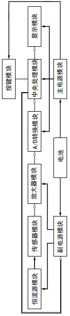
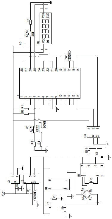
[0082] Figure 1~4 It is the best embodiment of the present invention, below in conjunction with attached Figure 1~4 The present invention will be further described.

[0083] exist figure 1 In the schematic block diagram of the micro-power consumption digital pressure gauge shown, the black arrow indicates the flow direction of the power supply signal, and the white arrow indicates the flow direction of the control signal. The micro-power consumption digital pressure gauge includes a power supply unit, a sensor unit and a data processing unit, the sensor unit is connected to the data processing unit, and the power supply unit supplies power to the sensor unit and the data processing unit at the same time. The power supply unit includes a battery and a main power module and an auxiliary power module connected to the battery. The main power module and the auxiliary power module are realized by a voltage stabilizing chip, which respectively convert the output voltage of the ba...


PUM


Abstract

The invention discloses a micro power digital pressure gauge and a pressure measuring method, and belongs to the technical field of pressure measuring. The micro power digital pressure gauge comprises a data processing unit, a sensor unit and a power supply unit. The pressure measuring method comprises the following steps: (1001) a system is initialized; (1002) whether a level changes on a port RB5 or not is detected; (1003) a key is pressed to start scanning; (1004) whether the sleeping time is finished or not is detected; (1005) sleeping is retained; (1006) AD sampling is started; (1007) whether the sampling is finished or not is detected; (1008) AD data are read; (1009) a constant-current source is turned off; (1010) a calculation is carried out for calibration; (1011) whether the calibration is finished or not is detected; (1012) real-time pressure is displayed; (1013) whether an interrupt flag is 1 or not is detected; (1014) the interrupt flag is set to 0. The micro power digital pressure gauge is powered by a battery, so that long-distance cable pavement is avoided, and the micro power digital pressure gauge is especially applicable to occasions having no use for pressure teletransmission.

Description

technical field [0001] A micro-power consumption digital pressure gauge and a pressure measurement method belong to the technical field of pressure measurement. Background technique [0002] As a conventional instrument for measuring pressure, pressure gauges are widely used in various industries. At present, there are two main types of products for measuring pressure in industry. One is mechanical pressure gauge. The conversion mechanism of the movement transmits the pressure deformation to the pointer, causing the pointer to rotate to display the pressure; the other type is a pressure transmitter that outputs an industrial standard signal (such as a 4~20mA current signal), through the pressure sensor inside and the transmitter The circuit board cooperates to transmit the monitored pressure remotely in the form of electrical signals. The prior art mechanical pressure gauges and pressure transmitters each have their own drawbacks. [0003] The traditional mechanical press...

Claims


Application Information

Patent Timeline
IPC IPC(8): G01L9/06
Inventor 王惜芳周秀成张志辉成韦
Owner 无锡市特种压力表有限公司
Learn More