
Small height detection method and system

A highly and tiny technology, applied in the field of microelectronics, can solve the problems of high cost and inability to detect quickly, and achieve the effect of low cost, improved test effect, and rapid detection.

Active Publication Date: 2015-05-27
SHENZHEN SINHOVO TECH CO LTD
View PDF5 Cites 4 Cited by
  • Summary
  • Abstract
  • Description
  • Claims
  • Application Information

AI Technical Summary

Problems solved by technology

[0011] The purpose of the embodiments of the present invention is to provide a detection method for a small height, which solves the problem of high cost and inability to detect quickly in the prior art

Method used


Image

  • Small height detection method and system
  • Small height detection method and system
  • Small height detection method and system

Examples


Embodiment Construction

[0032] In order to make the object, technical solution and advantages of the present invention clearer, the present invention will be further described in detail below in conjunction with the accompanying drawings and embodiments. It should be understood that the specific embodiments described here are only used to explain the present invention, not to limit the present invention.

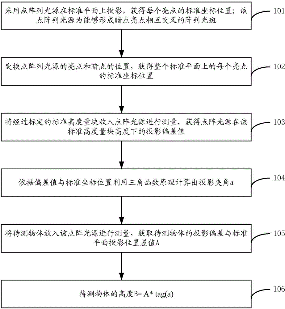
[0033] The specific embodiment of the present invention provides a detection method of tiny height, the method is as follows image 3 shown, including:

[0034] 101. Use a point array light source to project on a standard plane to obtain the standard coordinate position of each bright spot; the point array light source is an array spot that can form dark spots and bright spots intersecting each other (such as Figure 4 shown);

[0035] 102. Transform the positions of the bright spots and dark spots of the point array light source to obtain the standard coordinate position of each bright spot on t...


PUM


Abstract

The invention is applicable to the field of micro-electronics and provides a small height detection method and a small height detection system. The system comprises a digital camera and an array light source device, wherein an inclined angle is formed between the array light source device and the surface of a to-be-detected object; the array light source device sequentially comprises a high-brightness light source, a parallel light lens and a high resolution liquid crystal screen from interior to exterior; and the array light source device also comprises a liquid crystal drive circuit. The technical scheme provided by the invention has the advantages of low cost and fast detection.

Description

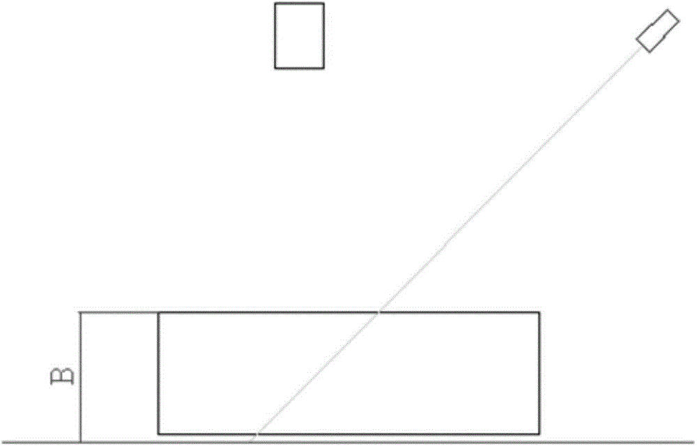
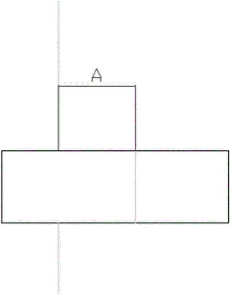
technical field [0001] The invention belongs to the field of microelectronics, in particular to a detection method and system for a small height. Background technique [0002] For the field of microelectronics, the measurement of micro-height is a common problem in practical technology. The existing micro-height measurement method mainly adopts the linear angle light source measurement method, that is, the measurement of the triangular principle. The principle is as follows: [0003] like figure 1 As shown, if you want to measure as figure 1 The height of B shown cannot be measured with ordinary calipers; therefore, an angle light source is generally used to measure the height with the triangular principle; figure 1 Shown: A linear light source illuminates the surface of the measured object at an angle a. Produces projections on both object surfaces and standard planes. Observing the projection from the camera above the object to be measured will produce the following ...

Claims


Application Information

Patent Timeline
Patent Type & Authority Applications(China)
IPC IPC(8): G01B11/03
Inventor 罗艺
Owner SHENZHEN SINHOVO TECH CO LTD
Learn More