Condensing lens and lamps

A technology of condensing lens and point light source, applied in the field of condensing lens, can solve problems such as affecting the condensing effect, and achieve the effect of ensuring the condensing effect and facilitating injection molding

Active Publication Date: 2018-10-23
SHENZHEN LANGHENG ELECTRICAL
View PDF1 Cites 0 Cited by
  • Summary
  • Abstract
  • Description
  • Claims
  • Application Information

AI Technical Summary

Problems solved by technology

However, this kind of lens structure will affect the light-gathering effect

Method used


Image

  • Condensing lens and lamps
  • Condensing lens and lamps
  • Condensing lens and lamps

Examples


Embodiment Construction

[0028] Now in conjunction with the accompanying drawings, the preferred embodiments of the present invention will be described in detail.

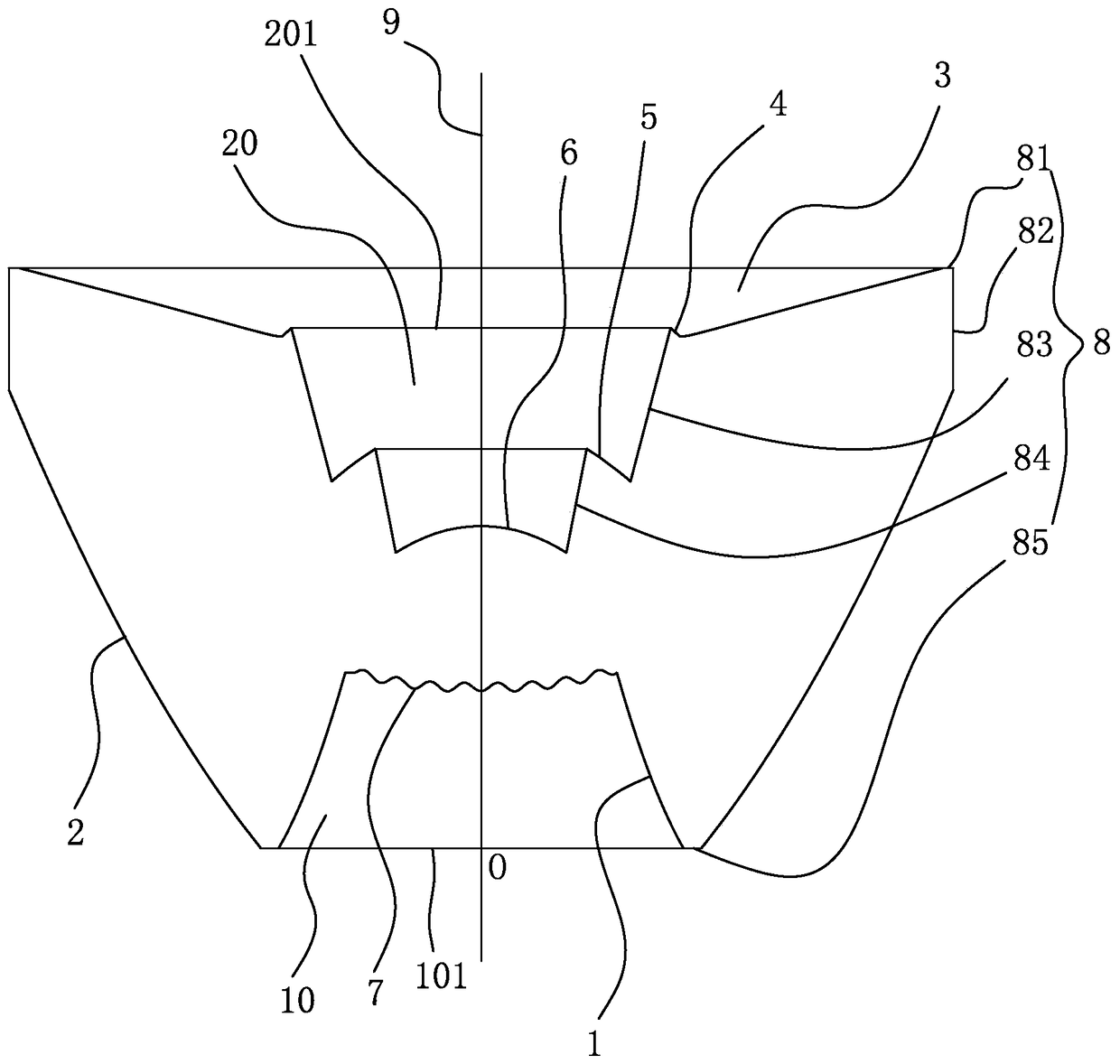
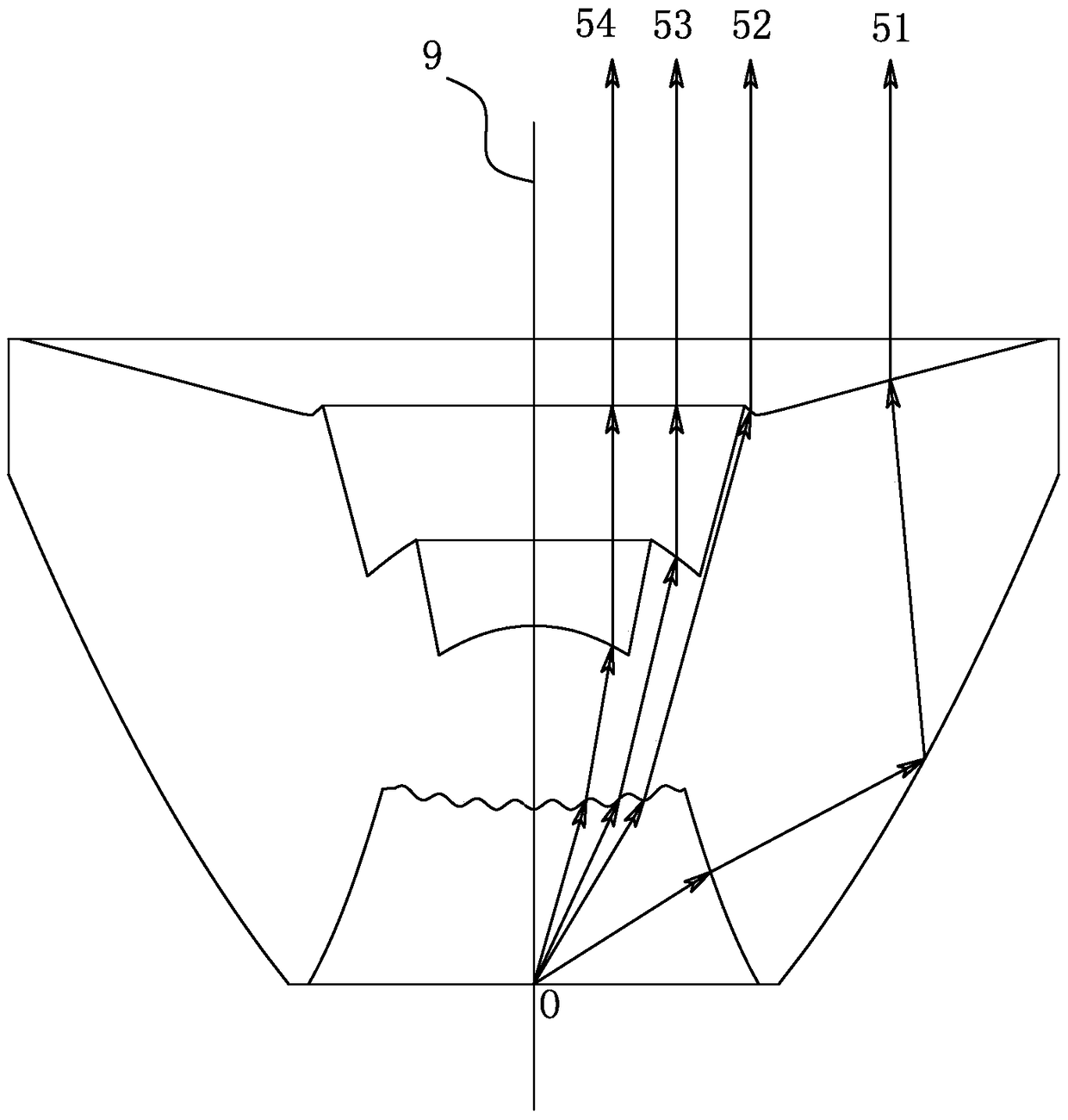
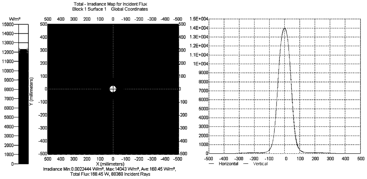
[0029] see Figure 1 to Figure 4 , figure 1 It is the partially cut-away structural intention of the condenser lens of the present invention. figure 2 for figure 1 Schematic diagram of the light output of the condensing lens and the light source. image 3 It is the light shape effect diagram of the combination of the condenser lens and the light source of the present invention. Figure 4 It is a light distribution curve diagram of the combination of the condenser lens and the light source of the present invention. The condensing lens of the present invention is a structure of revolution around an optical axis 9, the condensing lens has a first cavity 10 with a bottom opening 101 and a second cavity 20 with a top opening 201, the second cavity 20 A point light source (not shown) may be installed at the central point O of the bottom op...


PUM


Abstract

The invention relates to a condensing lens and a lamp. The condensing lens is a rotating body structure surrounding an optical axis and the condensing lens is provided with a first cavity, a second cavity, a first curved surface, a second curved surface, a third curved surface, a fourth curved surface, a fifth curved surface and a sixth curved surface, wherein the bottom of the first cavity is open; the top of the second cavity is open; the second cavity and the first cavity are oppositely formed at an interval along the optical axis; a point light source can be correspondingly arranged at the center point of an opening at the bottom of the first cavity; the first curved surface defines the lateral surface of the first cavity; the second curved surface is positioned outside the bottom of the condensing lens; the third curved surface is positioned at the top side of the condensing lens; the fourth curved surface is a step surface which is connected to the inner edge of the third curved surface and is positioned at the top side of the second cavity; the fifth curved surface is a step surface positioned at the middle part of the second cavity; the sixth curved surface is a step surface positioned at the bottom side of the second cavity. The condensing lens not only can be convenient for injection moulding, but also can ensure a condensing effect.

Description

technical field [0001] The invention relates to an optical system of a lamp, in particular to a condenser lens. Background technique [0002] At present, there are many known light-taking lenses for flashlights, but all of them have less curved surfaces and unreasonable distribution, resulting in thicker lens walls, which is not conducive to injection molding. For this reason, someone has proposed a thin lens structure, for example: Chinese patent CN201380002595.8 discloses a flashlight thin-section lens, which includes a substantially circular lens body, the lens body has a substantially concave front and a substantially convex rear, Wherein the lens body comprises: a central portion having a convex front surface adapted to direct the light beam in a desired direction, and an annular ring portion surrounding the central portion, wherein the annular ring portions collectively define a thickness dimension , wherein the thickness dimension varies by less than 20% of the lens ...

Claims


Application Information

Patent Timeline
Patent Type & Authority Patents(China)
IPC IPC(8): F21V5/04F21Y115/10
CPCF21V5/046F21Y2101/00
Inventor 岑亮兰观长刘宏军
Owner SHENZHEN LANGHENG ELECTRICAL
Why Eureka
Try Eureka