
Heat insulation structure for roofs

A technology of floor slabs and water storage pipes, applied in the direction of roof insulation materials, etc., can solve the problems of affecting indoor air and humidity, reducing the comfort of users on the top floor, and endangering the health of residents, so as to reduce the time of using air conditioners and improve indoor air. The effect that the environment and the heat insulation effect are excellent

Inactive Publication Date: 2015-05-27
XIAN ALL SAFE SCI & TECH
View PDF0 Cites 1 Cited by
  • Summary
  • Abstract
  • Description
  • Claims
  • Application Information

AI Technical Summary

Problems solved by technology

[0002] At present, many residents living in the city live in high-rise buildings. Because the top floors are relatively overheated, if no heat insulation treatment is done, the comfort of the top floor users in summer will be seriously reduced; most of the existing roofs are only made of hollow bricks. The heat insulation layer has very limited heat insulation effect, so residents living on the top floor often increase the use of air conditioners in summer to improve the sweltering indoor environment, but often turning on the air conditioner will bring many disadvantages: on the one hand, it will cause power consumption A large amount of energy is wasted. On the other hand, excessive blowing of the air conditioner will also affect the indoor air and humidity, and even cause harm to the health of the residents.

Method used


Image

  • Heat insulation structure for roofs

Examples


Embodiment Construction

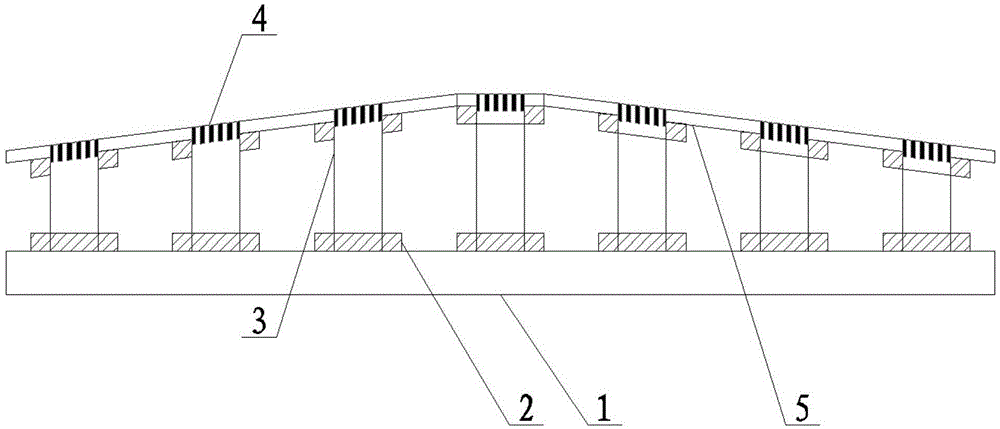
[0016] Such as figure 1 The shown heat insulation structure of a roof includes a floor 1 arranged on the uppermost layer of the roof structure, and heat-insulating tiles 5 are installed obliquely and symmetrically on both sides above the floor 1 , and between the heat-insulating tiles 5 and the floor 1 A plurality of water storage pipes 3 for storing water are installed in a vertical array, the water storage pipes 3 are all hollow structures, the tops of the water storage pipes 3 are all openings, and the bottoms of the plurality of water storage pipes 3 pass through The concrete 2 is fixed on the floor 1, and the top edges of the water storage pipes 3 are all fixed on the lower side of the heat-insulating tiles 5 through the concrete 2, and the opening positions of the heat-insulation tiles 5 correspond to a plurality of water storage pipes 3 Leakage holes 4 are all provided, and rainwater enters the inside of the water storage pipe 3 through the water leakage holes 4. The wa...


PUM


Abstract

The invention discloses a heat insulation structure for roofs. The heat insulation structure comprises a building slab arranged on the topmost layer of a roof structure, heat insulation ceramic tiles are obliquely and symmetrically mounted on both sides above the building slab, a plurality of water storage pipes for storing water are vertically mounted between the heat insulation ceramic tiles and the building slab in an arraying manner, the water storage pipes are hollow, openings are respectively formed in the tops of the water storage pipes, the bottoms of the water storage pipes are respectively fixed on the building slab with concrete, the top edges of the water storage pipes are respectively fixed on the lower side surfaces of the heat insulation ceramic tiles by using concrete, water leaking holes are respectively formed in the positions corresponding to the openings of the water storage pipes, on the heat insulation ceramic tiles, and rain water enters in the water storage pipes through the water leaking holes. According to the heat insulation structure disclosed by the invention, on one hand, heat is blocked by an interval structure, so that the heat insulation structure has the effect of heat insulation, and on the other hand, due to the evaporation of the stored rain water, the heat insulation structure has the effect of heat dissipation, so that users living in a top building can feel cool, and the using time of air conditioners in high-temperature weather is shortened.

Description

technical field [0001] The invention relates to the technical field of roof insulation systems, in particular to a roof insulation structure. Background technique [0002] At present, many residents living in the city live in high-rise buildings. Because the top floors are relatively overheated, if no heat insulation treatment is done, the comfort of the top floor users in summer will be seriously reduced; most of the existing roofs are only made of hollow bricks. The heat insulation layer has very limited heat insulation effect, so residents living on the top floor often increase the use of air conditioners in summer to improve the sweltering indoor environment, but often turning on the air conditioner will bring many disadvantages: on the one hand, it will cause power consumption On the other hand, excessive blowing of air conditioners will also affect the indoor air and humidity, and even cause harm to the health of residents. Contents of the invention [0003] The tec...

Claims


Application Information

Patent Timeline
Patent Type & Authority Applications(China)
IPC IPC(8): E04D13/16
Inventor 李卫红
Owner XIAN ALL SAFE SCI & TECH
Learn More