
Dual-rolling broom sweeping mechanism for sweeping vehicle

A cleaning mechanism and cleaning vehicle technology, applied in road cleaning, cleaning methods, construction and other directions, can solve the problems of inability to move up and down freely, high input costs, high maintenance costs, and achieve low cost, reduce energy consumption, and extend service life. Effect

Active Publication Date: 2015-05-27
福建省康洁环保科技有限公司
View PDF6 Cites 5 Cited by
  • Summary
  • Abstract
  • Description
  • Claims
  • Application Information

AI Technical Summary

Problems solved by technology

It has complex structure, high noise, high energy consumption, high input cost, high maintenance cost, and has high requirements on the use environment and the size and weight of dust; while the existing pure sweeping road sweeper is a single roller sweeping The cleaning system with integrated conveying roller brush, like the pure sweeping road sweeper of Tianjin Sweeping King, the obvious disadvantage of this kind of cleaning system integrating single roller sweep and conveying roller brush is that the whole mechanism is relatively cumbersome and the ground is uneven It is impossible to move up and down freely. When the operation is stopped, the cleaning mechanism and the conveying system must be lifted at the same time.
At the same time, it is also difficult for the single-roller sweeping mechanism to clean larger garbage.

Method used


Image

  • Dual-rolling broom sweeping mechanism for sweeping vehicle
  • Dual-rolling broom sweeping mechanism for sweeping vehicle
  • Dual-rolling broom sweeping mechanism for sweeping vehicle

Examples


Embodiment Construction

[0030] The present invention will be further described below in conjunction with the accompanying drawings.

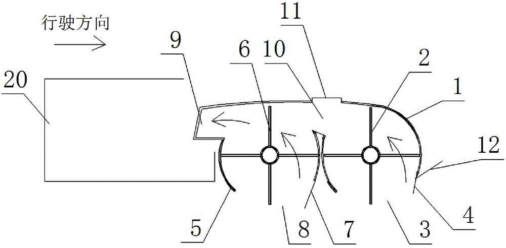
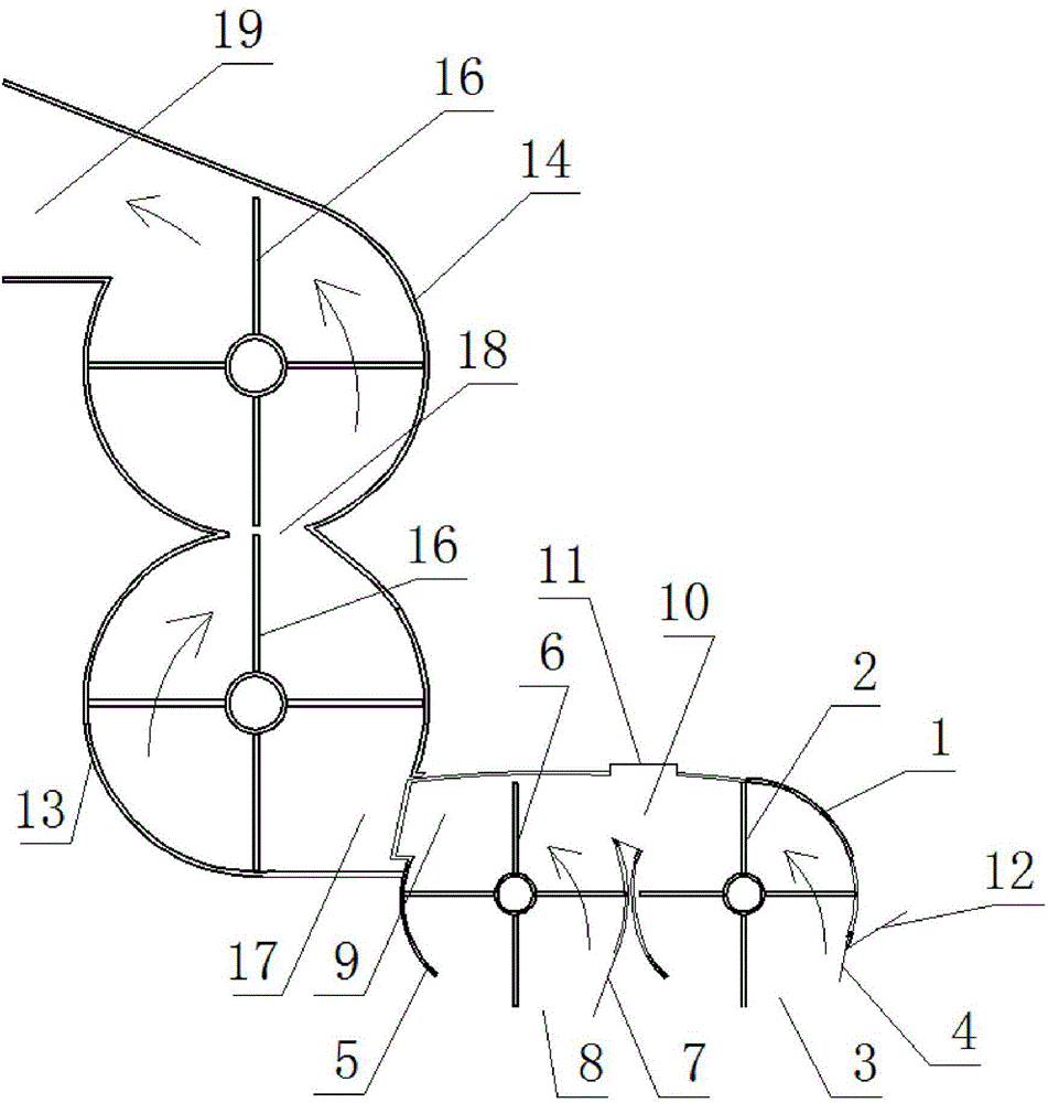
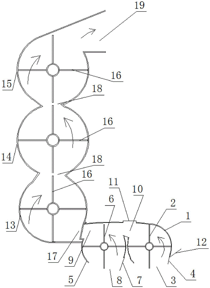
[0031] Such as figure 1 , figure 2 , image 3 Shown, a kind of sweeping vehicle double-roller sweeping cleaning mechanism of the present invention comprises by front rolling sweeping outer cover 1, forward rolling sweeping 2, forward rolling sweeping garbage inlet 3, forward rolling sweeping elastic dust guide plate 4, rear rolling sweeping The outer cover 5, the rear rolling sweep 6, the rear rolling sweeping elastic dust guide plate 7, the rear rolling sweeping garbage inlet 8, the rear rolling sweeping garbage outlet 9, etc., the front rolling sweeping 2 and the rear rolling sweeping 6 are the same 200810071548.X has the same or similar structure of the main and auxiliary rolling sweeps, but the rotation principle is different, and the garbage passage is completely different . The front rolling sweep cover 1 is connected with the rear rolling sweep cover 5, an...


PUM


Abstract

The invention discloses a dual-rolling broom sweeping mechanism for a sweeping vehicle. The dual-rolling broom sweeping mechanism comprises a front rolling broom outer cover, a front rolling broom, a rear rolling broom outer cover and a rear rolling broom, wherein a closed end plate is arranged at each of the two ends in the axial direction of each of the front rolling broom outer cover and the rear rolling broom outer cover; the dual-rolling broom sweeping mechanism is characterized in that the front rolling broom outer cover is connected with the rear rolling broom outer cover; the upper part of the front rolling broom outer cover is communicated with the upper part of the rear rolling broom outer cover through a front and rear rolling broom outer cover garbage through opening which is formed in an adjacent position; the openings formed in the positions, opposite to the ground, of the front rolling broom outer cover and the rear rolling broom outer cover are garbage inlets; a rear rolling broom garbage outlet is formed in the upper part of the rear rolling broom outer cover; the rotating directions of the front rolling broom and the rear rolling broom are opposite to the driving direction. Therefore, the front rolling broom and the rear rolling broom of the dual-rolling broom sweeping mechanism can move to clean up and down more freely along with the concave and the convex of the ground; the cleaning degree is improved; the energy consumption is reduced; the wear of hairbrushes can also be reduced; the damage to the rolling brooms can be reduced; the service lives of the rolling brooms can be prolonged.

Description

technical field [0001] The invention belongs to a double-roller cleaning mechanism of a sweeping vehicle, which is mainly used in road sweeping vehicles and can clean various dusts in different environments. Background technique [0002] Most of the existing road sweepers are suction type at present, and it is mainly made up of vacuum blower, sucker etc. It has complex structure, high noise, high energy consumption, high input cost, high maintenance cost, and has high requirements on the use environment and the size and weight of dust; while the existing pure sweeping road sweeper is a single roller sweeping The cleaning system with integrated conveying roller brush, like the pure sweeping road sweeper of Tianjin Sweeping King, the obvious disadvantage of this kind of cleaning system integrating single roller sweep and conveying roller brush is that the whole mechanism is relatively cumbersome and the ground is uneven Just can not move freely up and down, cleaning mechanism...

Claims


Application Information

Patent Timeline
Patent Type & Authority Applications(China)
IPC IPC(8): E01H1/04
CPCE01H1/045
Inventor 罗树基
Owner 福建省康洁环保科技有限公司
Learn More