Metal mask plate and organic electroluminescent display device manufactured by metal mask plate

A metal mask and image display technology, which is applied in the direction of electric solid-state devices, electrical components, semiconductor devices, etc., can solve the problems of unfavorable OLED display, limiting the width of OLED display frame, and large magnetic force.

Active Publication Date: 2015-05-27
BOE TECH GRP CO LTD +1
View PDF4 Cites 9 Cited by
  • Summary
  • Abstract
  • Description
  • Claims
  • Application Information

AI Technical Summary

Problems solved by technology

In the OLED evaporation process, it is usually necessary to use a magnetic spacer to absorb the entire metal mask to improve the sagging of the metal mask. Figure 1a As shown, the metal mask composed of strip-shaped slits 001 is easily affected by the magnetic force of the magnetic partition 002 during the process of being adsorbed and moved upward by the magnetic partition 002, because the strip-shaped slits 001 in the metal mask The shortest distance m of the side frame 003 parallel to it is generally greater than the distance n between adjacent strip slits 001, and the generated magnetic force is large, resulting in the deformation of multiple strip slits 001 close to the side frame 003 , which is not conducive to the preparation of high-resolution OLED displays
Therefore, if Figure 1b As shown, at least three strip-shaped slits adjacent to the side frame need to be provided in the corresponding non-display area A, so that the strip-shaped slits corresponding to the display area B will not be deformed, but this limits the width of the OLED display frame

Method used


Image

  • Metal mask plate and organic electroluminescent display device manufactured by metal mask plate
  • Metal mask plate and organic electroluminescent display device manufactured by metal mask plate
  • Metal mask plate and organic electroluminescent display device manufactured by metal mask plate

Examples


example 1

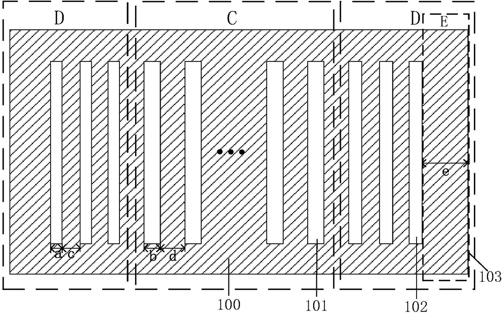
[0051] Such as Figure 2b As shown, the width b of the first strip slit 101 of the metal mask is 35 μm, the distance d between adjacent first strip slits 101 is 80.5 μm, and the width of the second strip slit 102 is a is 25 μm, the distance c between adjacent second strip-shaped slits 102 in the same second region D is 80.5 μm, and the width e of the side region E is less than 2.45 mm.

[0052] At this time, if the metal mask of this design is used for evaporation, the total width of the evaporated organic matter will be reduced by 60 μm compared to the original (because 6*(35-25)=60 μm), if the organic electroluminescent display is formed after packaging The frame of the device product will be reduced by 0.06mm.

example 2

[0054] Such as Figure 2dAs shown, the width b of the first strip slit 101 of the metal mask is 35 μm, the distance d between adjacent first strip slits 101 is 80.5 μm, and the width of the second strip slit 102 is a is less than 35 μm, the distance c between adjacent second strip-shaped slits 102 in the same second region D is less than 80.5 μm, and the width e of the side region E is less than 2.45 mm.

[0055] Such as Figure 3a with Figure 3b As shown, the metal mask of this design is combined with the magnetic spacer 104, and in the process of being attracted by the magnetic spacer 104 to move upward, it is assumed that three strip-like slits 101 are provided in each second region D. The second strip-shaped slits 102 parallel to each other, the area between the adjacent second strip-shaped slits 102 is R 1 , R 2 , R 3 , the dotted line is set as the central stress line of the area between the adjacent second strip-shaped slits 102 . for R 3 , the interaction force...


PUM

PropertyMeasurementUnit
widthaaaaaaaaaa

Abstract

The invention discloses a metal mask plate and an organic electroluminescent display device manufactured by the metal mask plate. The metal mask plate comprises a substrate, a first region arranged on the substrate and second regions arranged at the left and right sides of the first region respectively, wherein a plurality of parallel first strip slits which extend along the column direction and are mutually parallel are arranged in the first region, and at least three second strip slits which are mutually parallel to the first strip slits are arranged in each second region; at least two of the three conditions needs to be met: the width of each second strip slit is smaller than that of each first strip slit, a distance between two adjacent second strip slits in the same second region is smaller than that between two adjacent first strip slits, the width of each region at the side becomes narrow. According to the metal mask plate and the organic electroluminescent display device disclosed by the invention, when at least two conditions are met, the influence of a magnetic field on the second strip slits can be relieved, the second regions occupy little area, and narrow frame is realized in space.

Description

technical field [0001] The invention relates to the field of display technology, in particular to a metal mask plate and an organic electroluminescent display device produced therefrom. Background technique [0002] At present, organic electroluminescent display devices (Organic Electroluminescent Display, OLED) have gradually become the mainstream in the display field due to their excellent performances such as low power consumption, high color saturation, wide viewing angle, thin thickness, and flexibility. [0003] Evaporation technology is a key technology in the manufacturing process of OLED displays. OLED mainly uses red, green, and blue three-color light-emitting layers to achieve better luminous efficiency, and evaporation technology is mainly used in the film-forming process of red, green, and blue three-color light-emitting layers of organic light-emitting materials. In the film forming process, a high-precision metal mask (Fine Metal Mask, FMM) is mainly used for...

Claims


Application Information

Patent Timeline
Patent Type & Authority Applications(China)
IPC IPC(8): C23C14/04C23C14/24H01L51/56
CPCC23C14/042H10K71/166H10K50/00B05D1/32B05D1/60
Inventor 林治明
Owner BOE TECH GRP CO LTD
Why Eureka
Try Eureka