Bending Life Monitoring Method of Wire Rope for NC Ground Boring and Milling Machine

A steel wire rope and floor boring technology, which is applied in the field of wire rope bending life monitoring of CNC floor boring and milling machines, can solve the problems of lack of accurate and reliable data in the selection and maintenance of steel wire ropes, the inability to count the number of bending times of steel wire ropes, and the overdue service of steel wire ropes. Accurate maintenance, improved overall safety, and guaranteed safe operation

Active Publication Date: 2017-02-22
JIER MACHINE TOOL GROUP
View PDF6 Cites 0 Cited by
  • Summary
  • Abstract
  • Description
  • Claims
  • Application Information

AI Technical Summary

Problems solved by technology

The steel wire rope is frequently bent during the working process of the machine tool, and it is subjected to alternating loads for a long time, which will eventually cause the wire rope to fail due to fatigue damage.
Theoretical fatigue life of steel wire ropes is generally expressed by the number of bending times. In the past, due to the inability to accurately count the number of bending times of steel wire ropes, the selection and maintenance of steel wire ropes lack the support of accurate and reliable data. Replacement situation

Method used


Image

  • Bending Life Monitoring Method of Wire Rope for NC Ground Boring and Milling Machine
  • Bending Life Monitoring Method of Wire Rope for NC Ground Boring and Milling Machine
  • Bending Life Monitoring Method of Wire Rope for NC Ground Boring and Milling Machine

Examples


Embodiment Construction

[0020] The present invention will be further described below in conjunction with the accompanying drawings and embodiments.

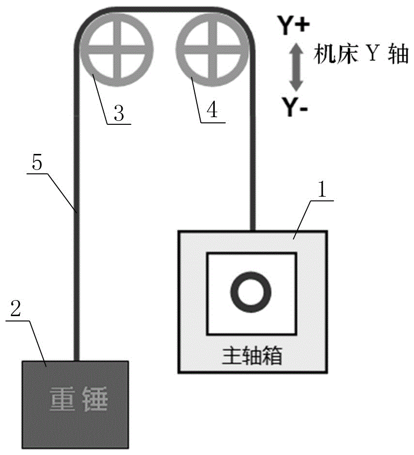
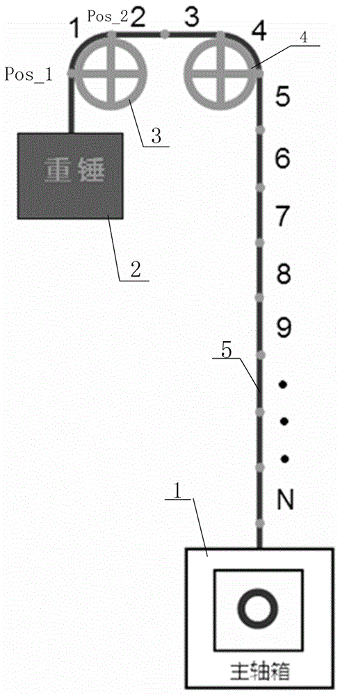
[0021] Such as figure 1 As shown, the schematic diagram of the structure of the spindle box in the CNC boring and milling machine is counterweighted by a steel wire rope, a fixed pulley and a weight. One end of the steel wire rope 5 is fixed to the spindle box 1, and the other end bypasses the first fixed pulley 3 After the second fixed pulley 4 is fixed with the weight 2, the headstock 1 is provided with a tool and a driving device that drives it to move along the Y-axis direction, and the weight 2 realizes the counterweight to the headstock 1, so that it Under the action, it is convenient to drive it to move along the Y-axis direction.

[0022] During the working process of the CNC boring and milling machine, the spindle box 1 will move up and down along the Y axis, so that the steel wire rope 5 will be bent on the first fixed pulley 3 and the second...


PUM


Abstract

The invention discloses a method for monitoring the bending life of a steel wire rope of a CNC (Computer Numerical Control) floor type boring and milling machine. The method comprises the steps of (a) dividing the steel wire rope into n zones for independently calculating the bending frequency; (b) judging whether bending is carried out or not; (c) reflecting the bending position of the steel wire rope; (d) calculating zones, which are subjected to the bending, on a first fixed pulley; (e) calculating zones, which are subjected to the bending, on a second fixed pulley; (f) calculating and judging the total bending frequency. According to the technology for monitoring the bending life of the steel wire rope used by the CNC floor type boring and milling machine, provided by the invention, the bending frequency of the steel wire rope in an overall length range can be recorded in real time and accumulatively calculated, the distribution situation of the bending frequency along the overall length of the steel wire rope can be displayed, alarm information can be transmitted when the maximum bending frequency is approximate to or is up to a theoretical limit value, real-time monitoring on the bending life of the steel wire rope is realized, the overall safety of products of the CNC floor type boring and milling machine can be increased, and an accurate and reliable data basis is provided for selecting and maintaining the steel wire rope.

Description

technical field [0001] The present invention relates to a method for monitoring the bending life of a wire rope of a CNC floor-mounted boring and milling machine, more specifically, a method for monitoring the bending life of a wire rope for a CNC floor-mounted boring and milling machine that can effectively count the bending times of each segment of the wire rope . Background technique [0002] The CNC floor boring and milling machine (usually referred to as floor boring) realizes the weight balance of the spindle box in the form of a heavy hammer, a pulley, and a wire rope. The wire rope is an important part of this balance system. The steel wire rope is frequently bent during the working process of the machine tool, and it is subjected to alternating loads for a long time, which will eventually cause the wire rope to fail due to fatigue damage. Theoretical fatigue life of steel wire ropes is generally expressed by the number of bending times. In the past, due to the inab...

Claims


Application Information

Patent Timeline
Patent Type & Authority Patents(China)
IPC IPC(8): B23Q17/00G06F19/00
CPCB23Q17/008
Inventor 周辉包鹏超
Owner JIER MACHINE TOOL GROUP
Why Eureka
Try Eureka