Support structure of glue-pumping device

A support structure and support plate technology, which is applied to the device and coating of the surface coating liquid, can solve the problems of low work efficiency and achieve the effect of improving work efficiency and facilitating replacement

Inactive Publication Date: 2015-05-27
WUXI HOUZHAI ZHENXIN MACHINERY
View PDF0 Cites 0 Cited by
  • Summary
  • Abstract
  • Description
  • Claims
  • Application Information

AI Technical Summary

Problems solved by technology

[0002] A barrel-mounted hot-melt adhesive gluing machine. The hot-melt adhesive material is packed in a barrel. The glue pumping device of the gluing machine includes a heating plate, a gear pump and a motor. The motor is fixed on the support seat, and the gear pump is fixed On the heating plate and driven by a motor, the heating plate cover is installed on the mouth of the hot melt adhesive barrel, and a sealing ring is embedded in the radial outer circumference of the heating plate. The sealing ring will expand due to the heating of the heating plate. When replacing the glue barrel At this time, it is necessary to align the mouth of the rubber barrel with the heating plate and smooth the sealing ring evenly to prevent the local protruding part of the sealing ring from being broken by the heating plate and the mouth of the rubber barrel. The heating plate and sealing ring enter the rubber barrel smoothly, and the work efficiency is low

Method used


Image

  • Support structure of glue-pumping device

Examples


Embodiment Construction

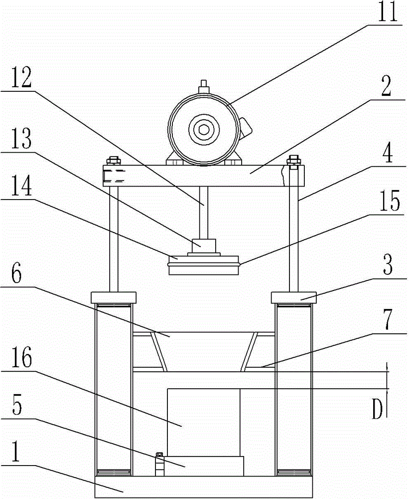
[0010] Such as figure 1 As shown, the supporting structure of the glue pumping device includes a base 1 and a support plate 2, the two ends of the base 1 are provided with a cylinder 31 and a cylinder 32, and the two ends of the support plate 2 are supported on the piston rods of the cylinder 31 and the cylinder 32 4. At the end, the motor 11 of the glue pumping device is fixed on the support plate 2, the positioning hoop 5 is installed on the base 1, and the guide hoop 6 is arranged above the positioning hoop 5. The heating of the positioning hoop 5, the guiding hoop 6 and the glue pumping device The disk 14 is coaxially distributed; the guide hoop 6 is an inverted cone shape, and the distance D between the bottom end surface of the guide hoop 6 and the upper end surface of the hot melt adhesive barrel 16 is 1.5 cm to 2 cm, and its inner diameter is the same as that of the hot melt adhesive barrel 16 The inner diameter is equal; the inner diameter of the positioning hoo...


PUM


Abstract

The invention provides a support structure of a glue-pumping device. The support structure can facilitate replacement of glue barrels and improve working efficiency. The support structure comprises a base and a support plate, wherein an air cylinder I and an air cylinder II are respectively arranged at two ends of the base, two ends of the support plate are supported on the ends of the piston rods of the air cylinder I and the air cylinder II, the base is provided with a locating hoop, the locating hoop, a guide hoop and a heating disc of the glue-pumping device are distributed coaxially, and the guide hoop is in the shape of an inverted cone.

Description

technical field [0001] The invention relates to the technical field of hot-melt adhesives, in particular to a hot-melt adhesive gluing machine, and in particular to a supporting structure of a glue pumping device on the gluing machine. Background technique [0002] A barrel-mounted hot-melt adhesive gluing machine. The hot-melt adhesive material is packed in a barrel. The glue pumping device of the gluing machine includes a heating plate, a gear pump and a motor. The motor is fixed on the support seat, and the gear pump is fixed On the heating plate and driven by a motor, the heating plate cover is installed on the mouth of the hot melt adhesive barrel, and a sealing ring is embedded in the radial outer circumference of the heating plate. The sealing ring will expand due to the heating of the heating plate. When replacing the glue barrel At this time, it is necessary to align the mouth of the rubber barrel with the heating plate and smooth the sealing ring evenly...

Claims


Application Information

Patent Timeline
Patent Type & Authority Applications(China)
IPC IPC(8): B05C11/10
Inventor 王惠峰
Owner WUXI HOUZHAI ZHENXIN MACHINERY
Why Eureka
Try Eureka