
Tab correction device

A technology of correction device and pole ear, which is applied in battery assembly, sustainable manufacturing/processing, climate sustainability, etc., can solve the problems of scrapping, low positioning accuracy, and high defect rate, etc., to save production costs, The effect of improving production efficiency and reducing defective rate

Pending Publication Date: 2020-12-04
EVE HYPERPOWER BATTERIES INC
View PDF0 Cites 0 Cited by
  • Summary
  • Abstract
  • Description
  • Claims
  • Application Information

AI Technical Summary

Problems solved by technology

[0003] However, as a common type of lithium-ion battery, cylindrical lithium-ion batteries are packaged mainly by manual, semi-automatic, and fully-automatic production processes. Due to the angle of the incoming material tabs of the winding core, positive and negative ear seals often occur during the production process. The phenomenon of oblique scrapping
Among them, in the packaging process of manual line or semi-automatic line, in order to avoid oblique scrapping of the ear seal, it is necessary to manually wrap the core in aluminum-plastic film and flatten the ear, which increases the cost of manual operation, has limited effect and poor appearance consistency. During the packaging process of the automatic line, the winding core directly relies on jig transfer, film feeding, and packaging. The angle of the tab before the winding core is inserted into the film is random, which increases the probability of sealing skew, and the positioning and packaging of the winding core is difficult. The positioning accuracy is low and packaging is difficult. During the production process It is easy to have the phenomenon of oblique ear seal & crushing and scrapping, which will easily lead to an increase in defective rate, resulting in low production efficiency and high production cost, which is not conducive to industrial production

Method used


Image

  • Tab correction device
  • Tab correction device
  • Tab correction device

Examples


Embodiment Construction

[0026] In order to facilitate the understanding of the present invention, the present invention will be described more fully below with reference to the associated drawings. Preferred embodiments of the invention are shown in the accompanying drawings. However, the present invention can be embodied in many different forms and is not limited to the embodiments described herein. On the contrary, the purpose of providing these embodiments is to make the disclosure of the present invention more thorough and comprehensive.

[0027] It should be noted that when an element is referred to as being “fixed” to another element, it can be directly on the other element or there can also be an intervening element. When an element is referred to as being "connected to" another element, it can be directly connected to the other element or intervening elements may also be present. The terms "vertical," "horizontal," "left," "right," and similar expressions are used herein for purposes of ill...


PUM


Abstract

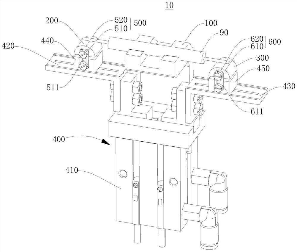
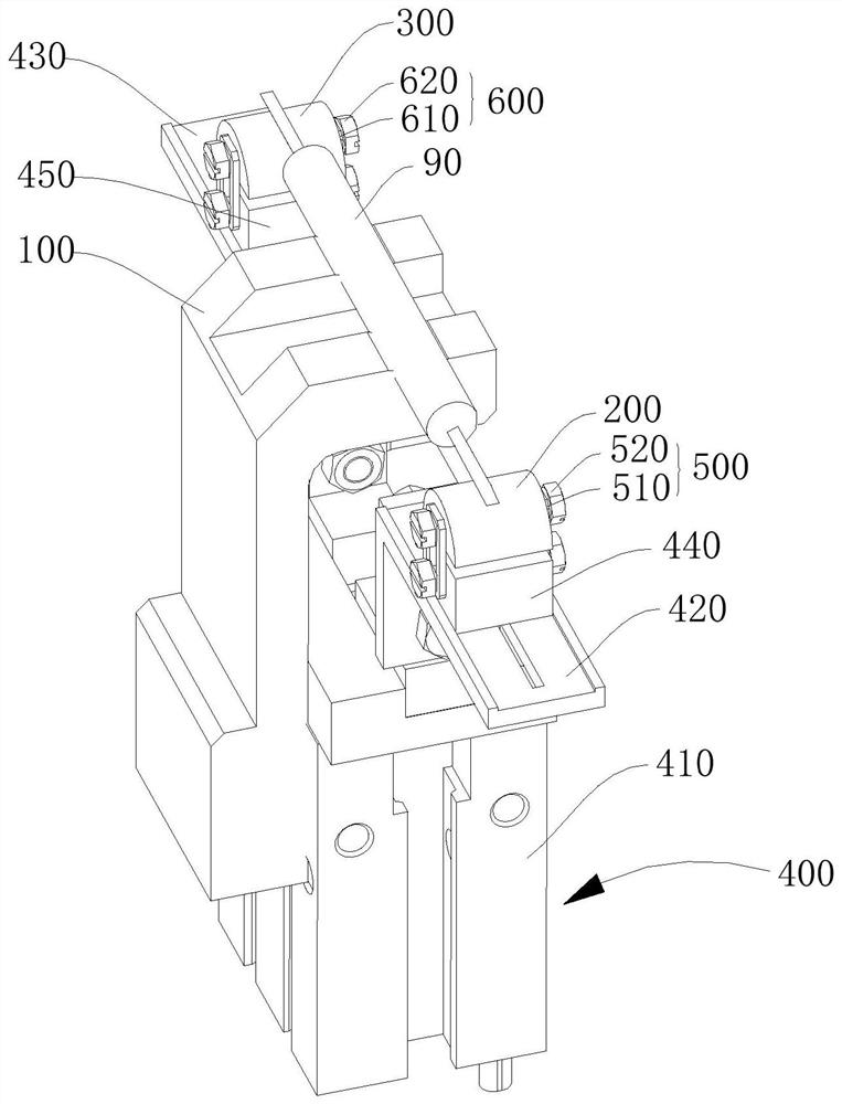
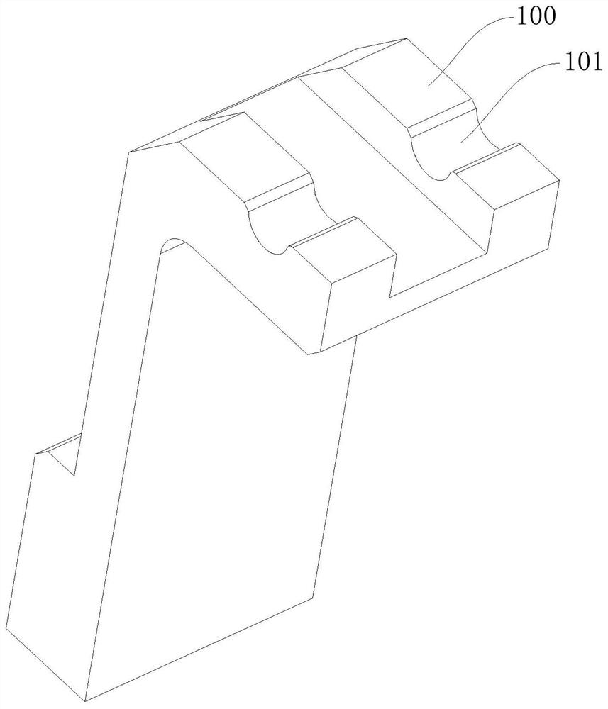
The invention provides a tab correcting device, comprising a material placing seat, a first correcting block, a second correcting block and a driving assembly, wherein a material placing groove is formed in the material placing seat; the first correcting block is arranged on one side of the material placing seat; the second correcting block is arranged on the other side of the material placing seat, and the second correcting block and the first correcting block are symmetrically arranged; and the driving assembly is adjacent to the material placing seat, connected with the first correcting block and the second correcting block and used for driving the first correcting block and the second correcting block to get close to each other or get away from each other. The material placing seat isarranged, the first correcting block and the second correcting block are symmetrically arranged on the two sides of the material placing seat, and the driving assembly drives the first correcting block and the second correcting block to move, so tabs at the two ends of a battery cell are smoothened, and bending is avoided; and the first correcting block and the second correcting block are symmetrically arranged, so a roll core can be moved to the center of the material placing seat, which is beneficial for subsequent accurately-positioned material taking and accurately-positioned material placing of the battery cell, prevention of deflection, reduction in a reject and improvement of production benefits.

Description

technical field [0001] The invention relates to the technical field of battery production equipment, in particular to a tab correction device. Background technique [0002] Lithium-ion batteries are usually composed of a positive electrode, a negative electrode, a separator, an electrolyte, and an outer package. The positive electrode, negative electrode, and separator are made into a battery cell through a winding process or a lamination process. The positive electrode and the negative electrode are respectively provided with positive and negative ears. The positive and negative tabs are the metal conductors that lead the positive and negative electrodes out of the battery, and are the contact points during charging and discharging. The energy density of lithium-ion batteries is relatively high and can be recycled. Lithium-ion batteries are widely used of a battery. [0003] However, as a common type of lithium-ion battery, cylindrical lithium-ion batteries are packaged ma...

Claims


Application Information

Patent Timeline
Patent Type & Authority Applications(China)
IPC IPC(8): H01M10/04H01M10/058
CPCH01M10/0404H01M10/058Y02E60/10Y02P70/50
Inventor 李日成陈兴刘建华刘金成
Owner EVE HYPERPOWER BATTERIES INC
Learn More